Knee orthosis

a knee and orthosis technology, applied in the field of knee orthosis devices, can solve the problems of lateral rotational and anterior instability of the knee, predisposing the joint to further instability and more serious injury, etc., and achieves superior medial, lateral, and rotational support. , to facilitate a more normal gait

Active Publication Date: 2012-11-13
NACE RICHARD NACE
View PDF15 Cites 7 Cited by
  • Summary
  • Abstract
  • Description
  • Claims
  • Application Information

AI Technical Summary

Benefits of technology

[0020]The present invention provides superior medial, lateral, and rotational support to the knee. A system of air bladders situated at mid-knee and below the knee can be inflated to provide the optimal brace support and protection of the knee joint in all planes for significant varied physical activities. At the same time, the present invention better facilitates a more normal gait with use of the brace through the means of an adjustable dynamic swing assist incorporated into the brace design when compared to the prior art.
[0021]The design of the new device includes a double upright design with a flexible posterior thigh cuff and a flexible anterior shin cuff with rigid uprights on both the medial and lateral side of the knee joint. An elastic anterior proximal thigh strap, an elastic distal posterior calf strap, static anterior thigh strap positioned between the proximal anterior elastic thigh strap and the patella, and a bioengineered semi-static calf strap located mid-way between the distal posterior calf strap and the crease of the knee joint provide bands of support encasing the rigid uprights above and below the knee joint. All of the straps are attached to the uprights with pivoting D rings which allow the straps to conform to changes in shape and angle of the leg during varied activities. A fifth adjustable static strap can be located on the anterior side of the leg just below the patella to provide an anterior lever arm to prevent forward tibial movement that is often seen with significant ACL injury or ACL ligament laxity.
[0022]A medial and lateral unicentric or polycentric hinge at the knee joint on each upright is aligned to allow normal flexion and extension movement of the knee. A flexion and extension range of motion control on one or both hinges allows the fitter to quickly and easily limit the motion of the knee to a specific range of flexion or extension that allows for safe flexion and extension of the knee.

Problems solved by technology

Knee laxity, due to ligament injury, can cause significant instability to the knee joint thereby predisposing the joint to further instability and more serious injury.
Injury to the MCL or LCL can result in lateral instability of the knee.
Injury to the ACL can result in rotational and anterior instability of the knee.
Injury to the PCL can result in posterior instability of the knee whereby the patient feels that the knee can “pop-out” of place.
It is also known that ligaments become more compliant with age, which can also lead to significant knee laxity.
Joint laxity reflects an impairment of the passive restraint system for which muscle activity may or may not compensate.
Knee joint laxity may adversely affect joint mechanics which can lead to an unstable knee joint and abnormalities in gait kinetics.
Knee instability, whether due to ligament injury, surgery or muscle weakness in the muscles supporting the knee joint during locomotion and other activities may require a supportive and protective knee orthosis device to prevent secondary damage to the knee resulting in more serious injury.
These rigid structures, which typically employ static straps, may immobilize the knee joint.
However, they lack the ability to flex and conform to the motions of a patient's muscular areas around the knee joint when the patient is walking, squatting or rising from a sitting position, let alone exerting a more rigorous motion such as running, dancing or performing any other motion required from someone engaged in a sport activity.
Simply put, the prior art braces lack any “dynamic conformability.” In other words, the prior art braces and their static straps do not conform to the ever changing, and often unpredictable, dynamics of the knee joint and the surrounding muscles there around.
And for these reasons, the prior art knee laxity and / or ligament braces are inadequate and are in great need of improvement.
Another troubling problem with the rigid structure of existing knee instability brace designs is that the braces can alter normal gait biomechanics.
Because they are rigid in design, and because of the dynamic motion of the knee and leg when walking, squatting, running, etc., the braces are prone to slippage and brace migration.
Simply put, the prior art braces do not conform to the constantly changing shape of the leg above and below the knee joint during motion.
Further, the greater the intensity of the body motion, the more likely brace slippage and migration will occur.
In spite of these innovations and supposed improvements, brace migration continues to be one of the most common complaints among brace users.
Brace migration during brace use can be extremely problematic for the patient.
If the condyle pads, which are also static in the prior art, become misaligned, optimal brace protection of the knee joint is compromised.
As the brace slips down, the axis of the brace and the axis of the knee joint will not align correctly, and this can place unwanted forces on the knee joint, which affect gait and the normal biomechanics of walking and other activities.
Patients can become noncompliant and will thus avoid wearing their brace because it is extremely inconvenient to constantly readjust the brace during certain activities.
This continues to be a problem, which clearly needs improvement thereupon.
In addition, no knee instability or knee ligament braces, which are currently available, are designed to maintain or strengthen the musculature of the leg, post injury or post surgery and during brace use.
Due to the fact that the gait of a patient having significant knee laxity or a knee ligament injury is usually altered as a means to avoid pain and re-injury of the knee joint, and further that known prior art rigid knee braces contribute to an abnormal and altered gait, full use of the leg muscles is significantly reduced, which then leads to significant muscle atrophy.

Method used


Image

  • Knee orthosis
  • Knee orthosis
  • Knee orthosis

Examples


Embodiment Construction

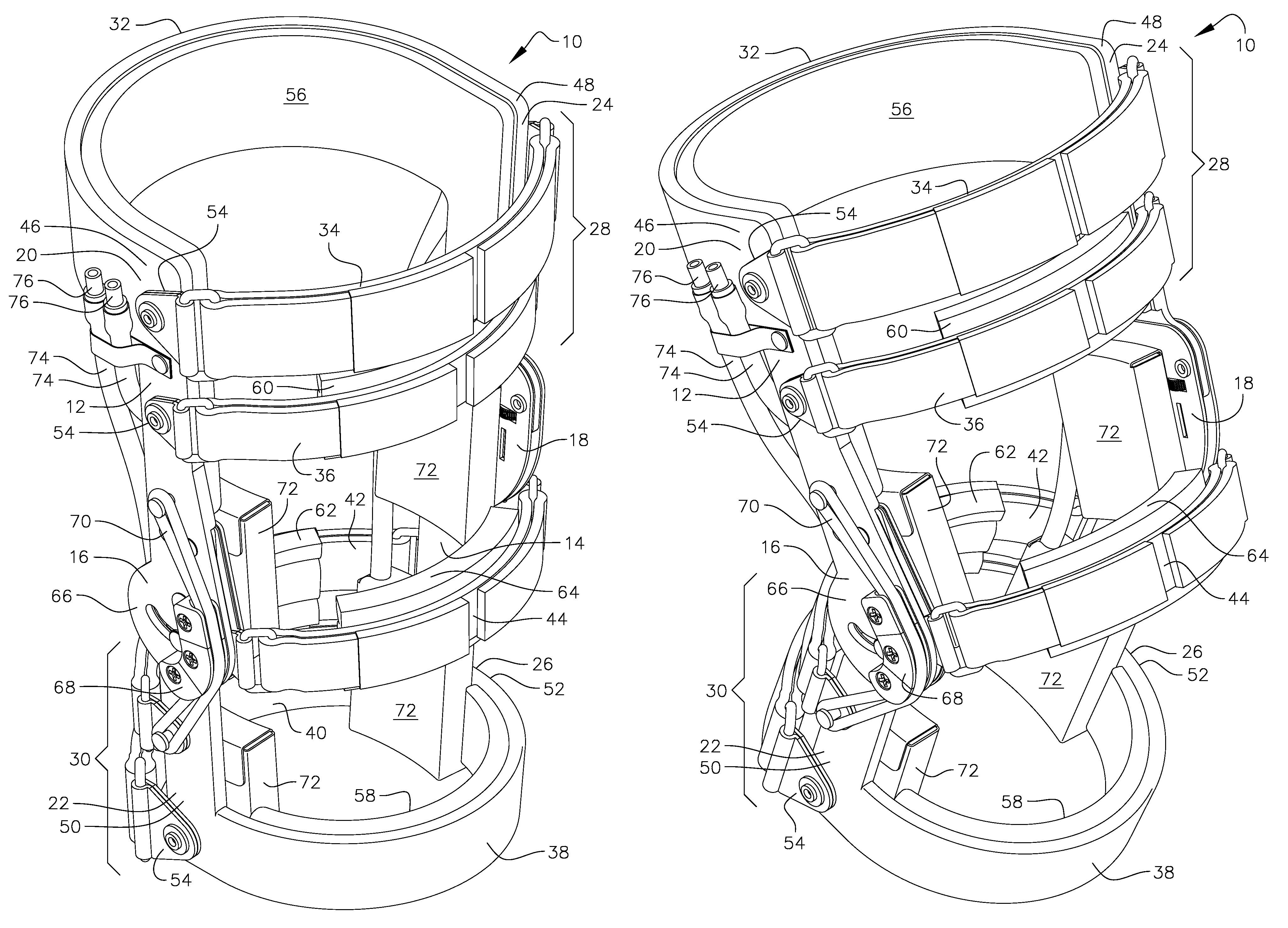
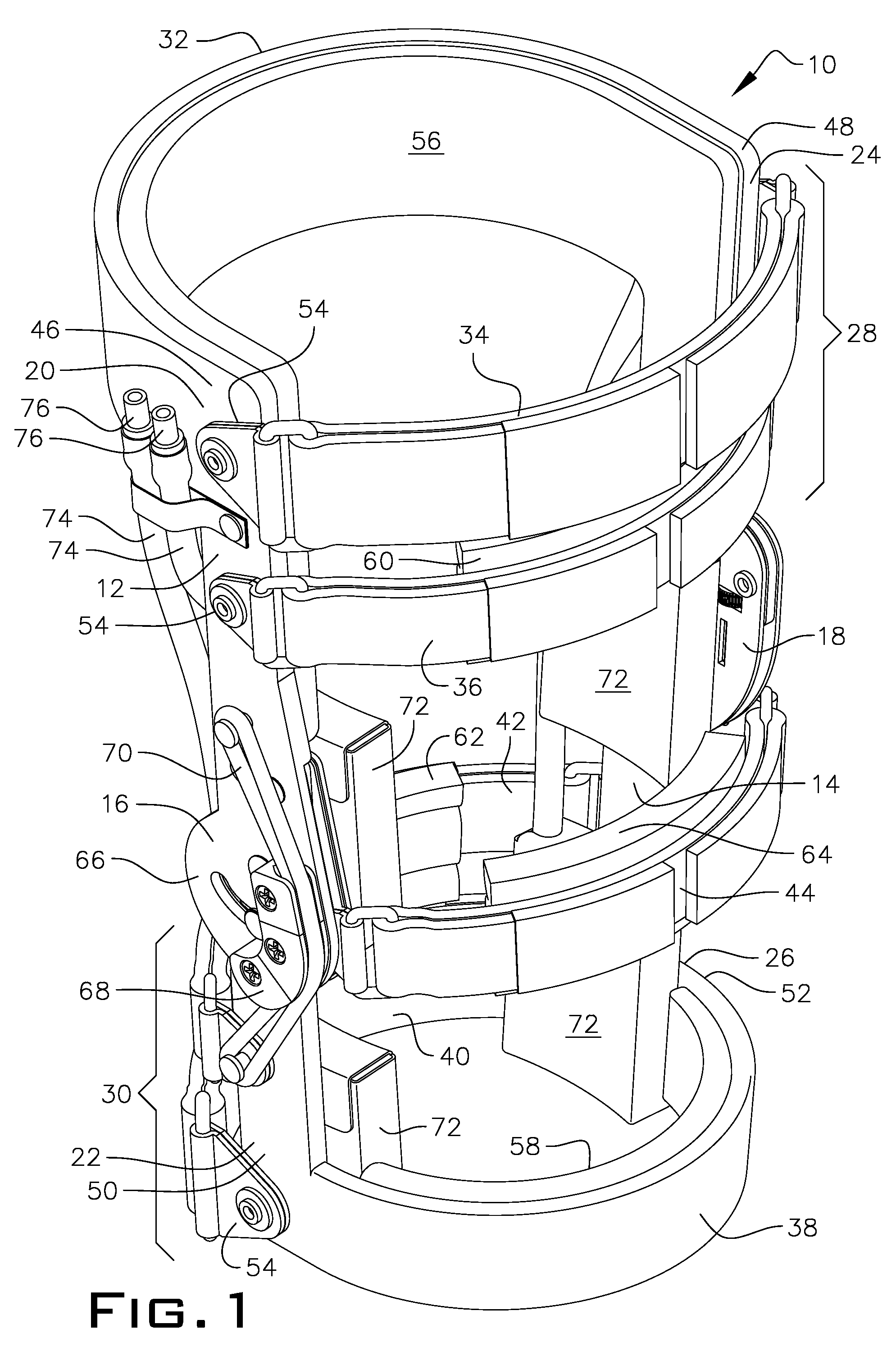
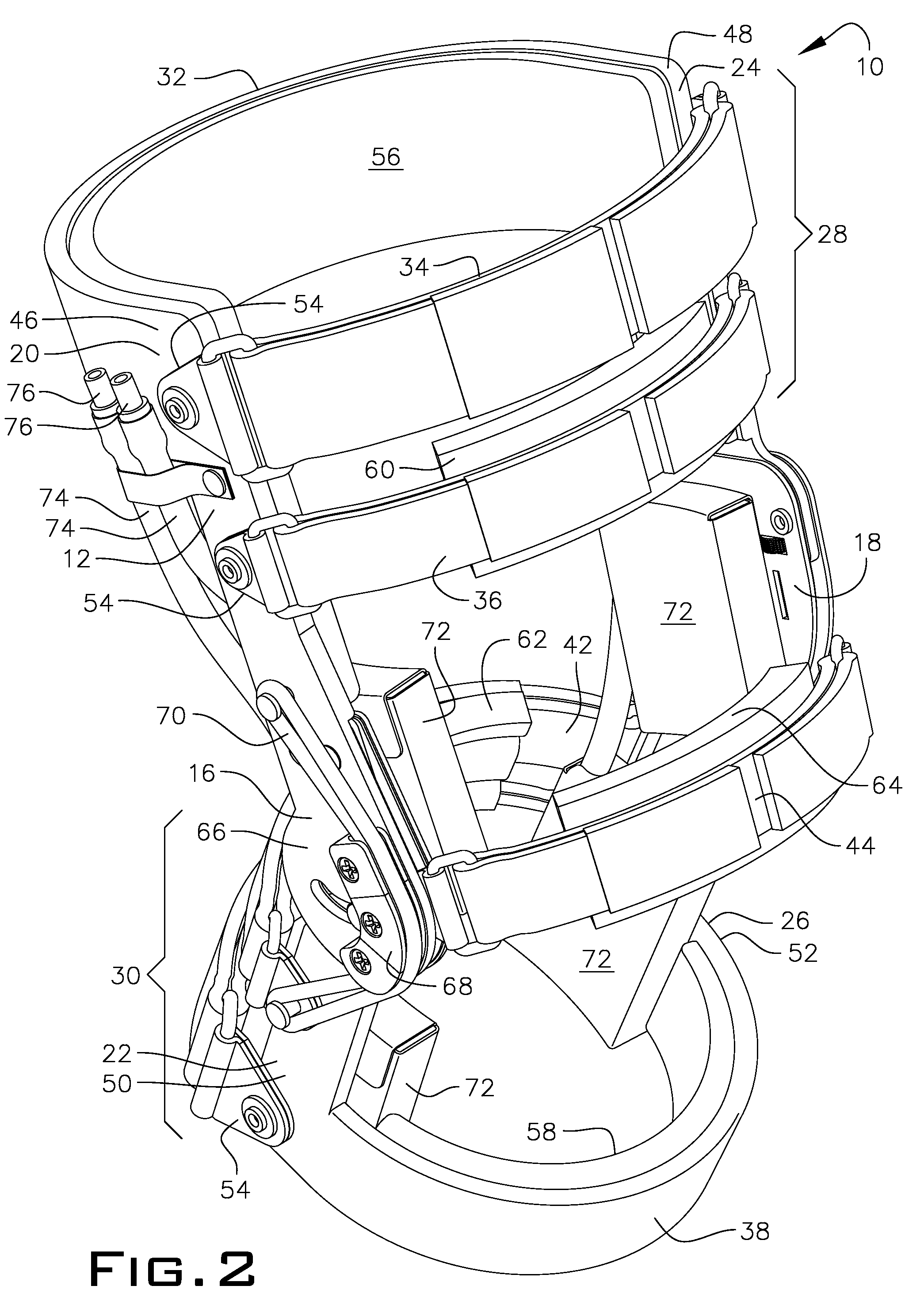
[0058]Throughout the following detailed description the same reference numerals refer to the same elements in all figures.

[0059]Referring to FIG. 1, a novel knee orthosis 10 of the present invention is shown, and hereinafter described, for use with a patient with a knee injury or for employment on leg of patient before or after surgery. It is important to note immediately that the novel knee orthosis 10 of the present invention can be used on the same patient before and after a surgical procedure to replace or repair an injured or diseased knee joint. No knee orthosis or brace hereto before has ever contemplated, let alone be employed, the use of the same orthotic device for pre and post-surgery. Therefore, knee orthosis 10 has all of the advantages as set forth above in the Summary of the Invention and improves upon and fixes all of the deficiencies as also described above, but generally discussed in the Background of the Art.

[0060]Knee orthosis 10, in a preferred embodiment, emplo...


PUM


Abstract

A knee orthosis device provides medial, lateral, and rotational control of a knee joint. The novel knee orthosis device stabilizes an injured or surgically repaired, or a weakened knee joint having a neurological disability, which causes instability therein, by applying adjustable corrective and therapeutic forces, which operate to stabilize and protect the knee as well as to correct abnormal gait and to rehabilitate the knee joint and surrounding muscles above and below the knee by encouraging and recruiting said muscles to operate again more normally through the use of a dynamic swing assist mechanism. The knee orthosis also provides dynamically conformable thigh and shin cuff circumferential band systems in combination with a multitude of other elements that conform to the constant dimensional changes of the muscle groups that are surrounded by the knee orthosis device during ambulatory or athletic motion.

Description

FIELD OF THE INVENTION[0001]The present invention relates to a knee orthosis device used to provide medial, lateral, and rotational control of a knee joint. More particularly, it relates to a knee orthosis device used for stabilizing an injured or surgically repaired, or a weakened knee joint having a neurological disability, which causes instability therein, by applying adjustable corrective and therapeutic forces, which operate to stabilize and protect the knee as well as to correct abnormal gait and to rehabilitate the knee joint and surrounding muscles above and below the knee by encouraging and recruiting said muscles to operate again more normally.BACKGROUND OF THE INVENTION[0002]Orthotic devices and appliances commonly referred to as “orthotics,” are known in the prior art and have been utilized for many years by orthotists (a maker and fitter of orthotics), physical therapists, and occupational therapists to protect an injured or surgically repaired knee joint, or a weakened...

Claims


Application Information

Patent Timeline
Patent Type & Authority Patents(United States)
IPC IPC(8): A61F5/00
CPCA61F5/0123A61F2005/0167A61F2005/0174A61F2005/0179
Inventor NACE, RICHARD A.
Owner NACE RICHARD NACE
Why Eureka
Try Eureka