Wireless control system and method in an illumination network

a wireless control and illumination network technology, applied in the field of wireless control techniques, can solve the problems of affecting the popularization and application of such a new system, so as to achieve the effect of being easily appreciated

Inactive Publication Date: 2012-11-20
KONINK PHILIPS ELECTRONICS NV
View PDF10 Cites 0 Cited by
  • Summary
  • Abstract
  • Description
  • Claims
  • Application Information

AI Technical Summary

Benefits of technology

[0016]Other objects and effects of the invention will become more apparent and easily appreciated by referring to the following description taken in conjunction with the accompanying drawings and the claims and with a better understanding of the invention.

Problems solved by technology

Traditionally, the console and the nodes are connected via cables, and such connection may bring many engineering difficulties and troubles to the system in its installation, commissioning and maintenance.
Although the wireless control system is very attractive, it still has many pending problems concerning display when being applied to an illumination network, for example, the data rate, the communication distance, the cost control and the time needed for commercializing, etc.
Theoretically, a brand new wireless control system can be developed specially for the illumination networks, but the high cost and the long time for commercializing will hinder the popularization and application of such a new system.
However, the existing wireless network protocols have some serious problems when being directly applied to illumination networks, especially large-scale illumination networks.
However, the TDMA system that can support a data rate exceeding 6 Mbps is too expensive to be suitable for use in such an application, and in practice there is no FDMA system that can simultaneously support 10,000 channels with each channel operating at 600 bps at present, and customizing such FDMA systems to different illumination networks will require a long developing period and a high cost.
In addition, expansibility of the TDMA and FDMA systems is very limited.

Method used


Image

  • Wireless control system and method in an illumination network
  • Wireless control system and method in an illumination network
  • Wireless control system and method in an illumination network

Examples


Embodiment Construction

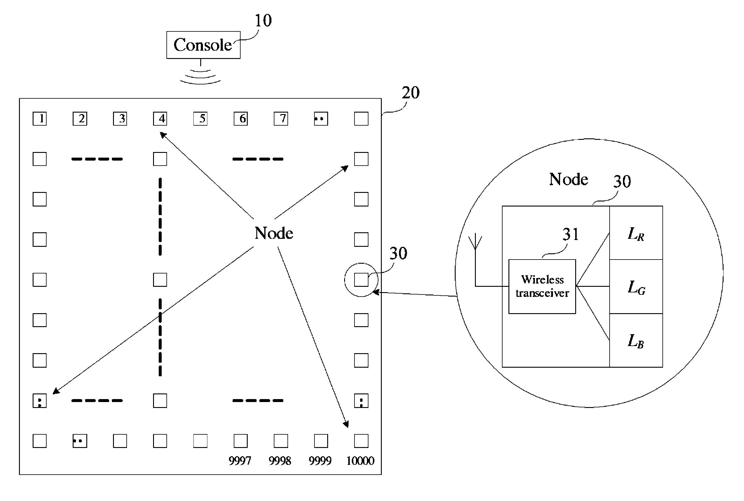
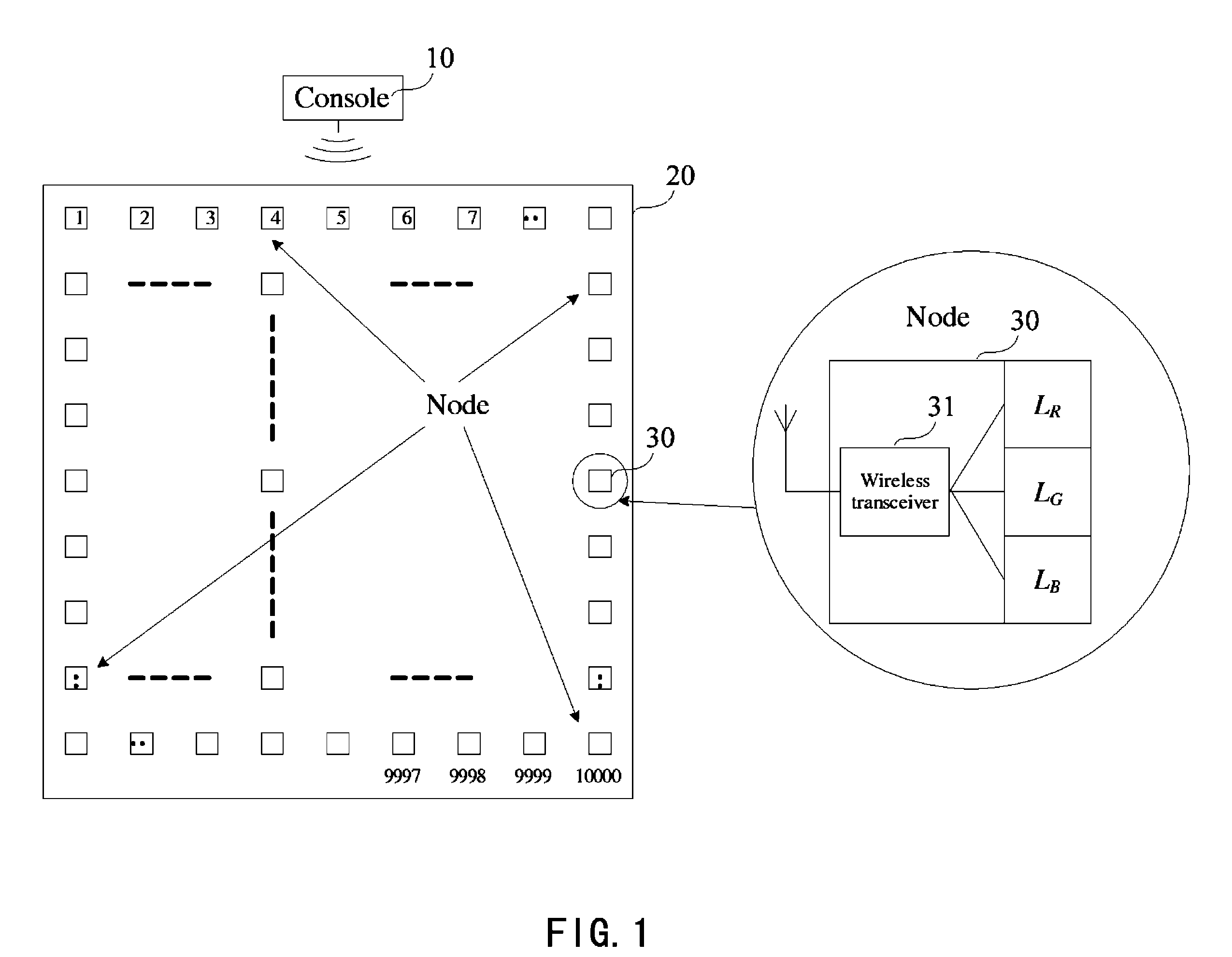
[0023]The previously mentioned illumination network comprising one console and 10,000 nodes is still used herein as an example to illustrate in detail the operating principle of the wireless control system of the present invention when it is applied to the illumination network.

[0024]Referring to FIG. 1, the illumination network comprises a console 10 and a screen 20 formed of 10,000 nodes 30. The console 10 can transmit data signals to each node 30 to respectively control changes of its brightness and color, thereby making the screen 20 to display corresponding profiles. Each node 30 comprises a wireless transceiver 31 and three lamps LR, LG and LB of red, green and blue. The brightness of said three lamps is controlled by a 24-bit signal received by the wireless transceiver 31.

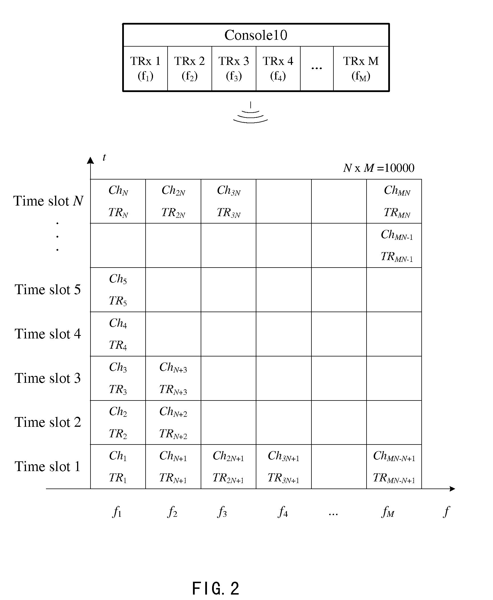
[0025]The wireless control system of the present invention is mainly used for establishing a wireless connection between the console 10 and the nodes 30 in the illumination network, so that the console 10 can...


PUM


Abstract

The present invention proposes a wireless control system and method which may be mainly used in illumination networks. The wireless control system and method of the invention distributes data signals to be transmitted at a control terminal in different time slots of different frequencies for transmission, while each node in the system will only receive its corresponding data signal in a predetermined time slot of a predetermined frequency. Thus a high operating rate can be obtained at the control terminal while maintaining the operating rate of the node unchanged. This helps to greatly reduce the cost of the wireless transceiver of each node, thereby correspondingly reducing the cost of the whole system and realizing a high expansibility.

Description

TECHNICAL FIELD[0001]The present invention relates to a wireless control technique, in particular to a wireless control system and method for use in an illumination network.BACKGROUND ART[0002]Centrally controlled illumination networks are being widely used recently, such a control mode allowing the user to control the illumination networks in real time to display different illumination profiles. A main feature of a control system using such a control mode is that the data rates for communication between a console and nodes are asymmetrical, because generally there is only one or a few consoles, comparing to a large number of nodes (thousands or even tens of thousands).[0003]Traditionally, the console and the nodes are connected via cables, and such connection may bring many engineering difficulties and troubles to the system in its installation, commissioning and maintenance. With the development of the wireless communication technique, people began to explore whether a wireless co...

Claims


Application Information

Patent Timeline
Patent Type & Authority Patents(United States)
IPC IPC(8): G09G5/00
CPCH04J4/00H05B37/0272H05B47/19
Inventor QIAN, XUECHENGFENG, LEI
Owner KONINK PHILIPS ELECTRONICS NV
Why Eureka
Try Eureka