
Apparatus for block-selected encoding of a digital video signal

a video signal and video encoding technology, applied in the field of video signal encoding methods, can solve the problems of lack of encoding support for compound images, lack of dynamic images, complex and difficult management of personal computers, etc., to save both save memory and memory bandwidth, and optimize bandwidth consumption

Active Publication Date: 2012-11-20
TERADICI CORP
View PDF35 Cites 2 Cited by
  • Summary
  • Abstract
  • Description
  • Claims
  • Application Information

AI Technical Summary

Benefits of technology

[0013]The primary objective of the present invention is to provide non-intrusive methods and apparatus for encoding a digitized raster display signal that may then be transmitted from a host data processing system to a remote display across a communications link. There are a number of aspects to the present invention. In one aspect, the invention detects persistent blocks of pixels in a real-time digital raster signal and uses progressive encoding sequences to transmit and build persistent blocks. This aspect of the invention brings the human perception and bandwidth efficiency benefits of progressive encoding methods used in still image compression to the compression of a dynamic computer display image.
[0015]In another aspect, the invention provides a selectable quality encoder that enables the number of encoded bit planes for a frame to be dependent on the bandwidth availability at the time. This allows the rapid build of recently updated areas of a computer display in the case where other areas are persistent and optimized bandwidth consumption in the case where large areas of the display are updated. Unlike methods that use pixel by pixel comparisons for detecting persistent images, the invention saves the memory bandwidth required to load previously stored images. One embodiment of the invention enables a progressive build system to operation without a stored image at the encoder which saves both memory and memory bandwidth.

Problems solved by technology

Continued advances of this computer technology have made these personal computers very powerful but also complex and difficult to manage.
However, a fundamental shortcoming is a lack of support for dynamic images.
Another shortcoming lies in the lack of encoding support for compound images comprised of text, pictures, background and high definition icon types.
They are relatively insensitive to encode / decode delays and typically use encoding methods unrelated to this discussion.
Consequently, these offer limited compression and tend to consume high network bandwidth in applications that mandate high frame rates.
This is impractical for sending a normal resolution display image at a reasonable refresh rate.
For example, an SXGA image frame of 1280×1024 at 24-bit resolution would take 0.3 seconds of dedicated 100 Base T LAN network bandwidth, making perception-free communications of display information impossible.
However, this method is intrusive on the host system which requires operating system dependent graphic command routing software.
Moreover, a processor and software capable of interpreting the graphics commands is required at the remote user interface which makes the method restrictive in its broad compatibility, adds cost and increase complexity to the remote installation.
This decreases the overall amount of data, especially for a computer display in which much of the display may be static from frame to frame.
However, this approach is expensive to implement because the data processor requires at least two frame buffers namely a first containing a copy of the previously communicated frame and a second containing the present frame.
Given that the previous frame must be compared with the present frame one pixel at a time, possibly requiring an additional temporary delta-buffer, this approach is both memory and computationally intensive.
There is a noticeable decrease in the performance of applications running on the data processor, especially during applications such as video clips that involve significant screen refresh activity.
These tiling and list methods are limited.
This further reduces the performance of the data processor.
Existing tiled change detect methods are also limited in sophistication.
In summary, existing still image and video compression techniques are not optimized for the high-quality and low latency encoding requirements of dynamic computer display images.
This results higher equipment and maintenance costs and lower performance.

Method used


Image

  • Apparatus for block-selected encoding of a digital video signal
  • Apparatus for block-selected encoding of a digital video signal
  • Apparatus for block-selected encoding of a digital video signal

Examples


Embodiment Construction

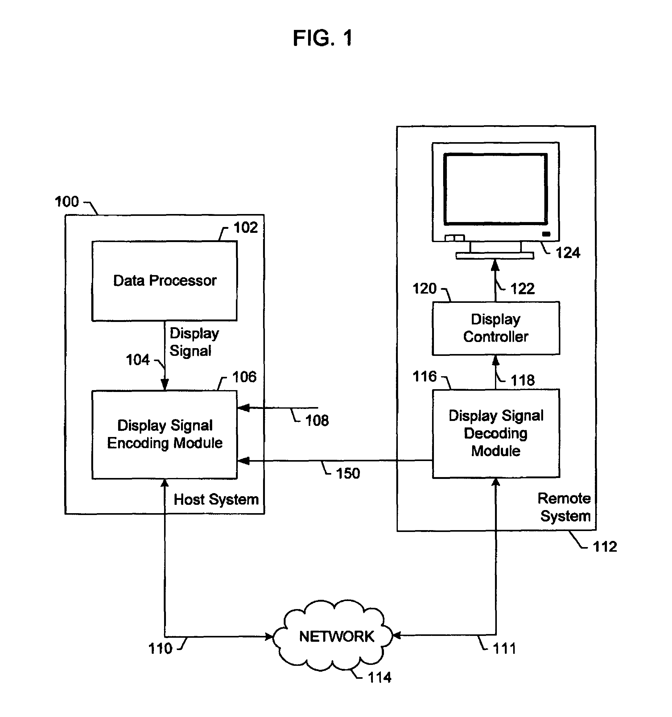
[0026]FIG. 1 presents a system architecture of one embodiment of the invention. In the embodiment described, a display signal encoding module enables the transfer of computer display images from a host data processor to a remote display system. However, the invention is also applicable to other media transport systems, for example recording, storage or archival systems.

[0027]Referring to FIG. 1, host system 100 has data processor 102 with digital display output signal 104. In the described embodiment, digital display output signal 104 is a Digital Visual Interface (DVI) output signal. In alternative embodiments, digital display output signal 104 may be other display interfaces such as VESA Digital Packet Video Link (DPVL), High Definition Multimedia Interface (HDMI), Unified Display Interface (UDI), DisplayPort, IEEE1394 / Firewire™ or others. In another alternative embodiment, digital display output signal 104 may be a bus interface that uses a DMA controller to access a frame buffer...


PUM


Abstract

An image encoding apparatus. In one embodiment, the apparatus comprises an encoding engine coupled to a source of a block of pixel data, the encoding engine enabled to encode the block of pixel data to a quality level, the encoding engine coupled to a network interface; and a state sequencer, the state sequencer enabled to obtain an indication of scan block persistence, build state information and encoding parameters to control the quality level.

Description

CROSS-REFERENCE TO RELATED APPLICATIONS[0001]This application is a divisional of U.S. patent application Ser. No. 11 / 532,865, filed Sep. 18, 2006, now U.S. Pat. No. 7,822,278 entitled “Methods and Apparatus for Encoding a Digital Video Signal”, which (i) is a Continuation-in-Part of Ser. No. 11 / 333,955 filed Jan. 17, 2006, now U.S. Pat. No. 7,747,086, issued Jun. 29, 2010, entitled “Methods and Apparatus for Encoding a Shared Drawing Memory,” which claims priority to Provisional Patent Application Ser. No. 60 / 703,767, filed Jul. 28, 2005; and (ii) claims priority to Provisional Patent Application Ser. No. 60 / 719,050, filed Sep. 20, 2005, entitled “Methods and Apparatus for Using Hash Codes to Enable Progressive Build,” and Provisional Patent Application No. 60 / 726,418, filed Oct. 12, 2005, entitled “Sequenced Progressive Encoding Methods”. Each of the aforementioned related patent applications is herein incorporated by reference in its entirety.BACKGROUND OF THE INVENTION[0002]1. Fi...

Claims


Application Information

Patent Timeline
Patent Type & Authority Patents(United States)
IPC IPC(8): G06K9/36G06K9/46
CPCH04N19/176H04N19/149H04N19/34H04N19/166H04N19/507H04N19/12H04N19/196H04N19/124
Inventor HOBBS, DAVID VICTORRATTO, PATRICK
Owner TERADICI CORP
Learn More