
Superconducting composite, preliminary product of superconducting composite and method for producing same

a superconducting composite and composite technology, applied in the direction of superconductors/hyperconductors, superconducting magnets/coils, magnetic bodies, etc., can solve the problems of high equipment and cooling costs, difficult to produce large conductor strands with homogenous conductor properties for power engineering by means of classic wire manufacturing methods, and the ability to shape with little or no ability to achieve the classic shaping method. , to achieve the effect of reducing the risk of damage to the super

Inactive Publication Date: 2012-11-27
BRUKER EAS
View PDF13 Cites 0 Cited by
  • Summary
  • Abstract
  • Description
  • Claims
  • Application Information

AI Technical Summary

Benefits of technology

"The patent text describes a new method for producing a superconductor composite that can be used in magnetic and power engineering. The composite is made up of a core made of a superconducting material called MgB2, surrounded by a non-superconducting alloy. The method involves creating a composite with a two-dimensional composition distribution, where the magnesium content is higher in the inner area of the non-superconducting alloy that surrounds the core. This allows for better distribution of current and reduces the risk of damage to the superconducting phase. The preliminary product of the composite can be made by surrounding a rod with the non-superconducting alloy and then annealing it. The technical effect of this patent is the production of a reliable and efficient superconductor composite that can be used in practical applications."

Problems solved by technology

However, the low transition temperature leads to high equipment and cooling costs.
The disadvantage of the MgB2 phase, however, is that it shows little or no ability to be shaped using the classic shaping methods such as rolling, thermoforming or extruding.
Producing large conductor strands with homogenous conductor properties for power engineering by means of classic wire manufacturing methods is not easy.

Method used


Image

  • Superconducting composite, preliminary product of superconducting composite and method for producing same
  • Superconducting composite, preliminary product of superconducting composite and method for producing same
  • Superconducting composite, preliminary product of superconducting composite and method for producing same

Examples


Embodiment Construction

[0040]In certain embodiments, the first casing and the second casing cannot be easily recognized as separate parts inside the composite, e.g., if the materials of the two casings are welded to one another following shaping. Also, the materials of the two casings may fuse due to the heat treatment, so that a boundary between the two cannot be recognized in a microsection, for example.

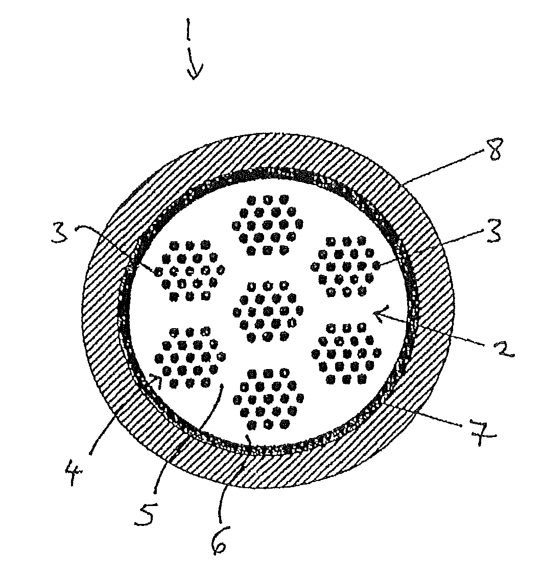
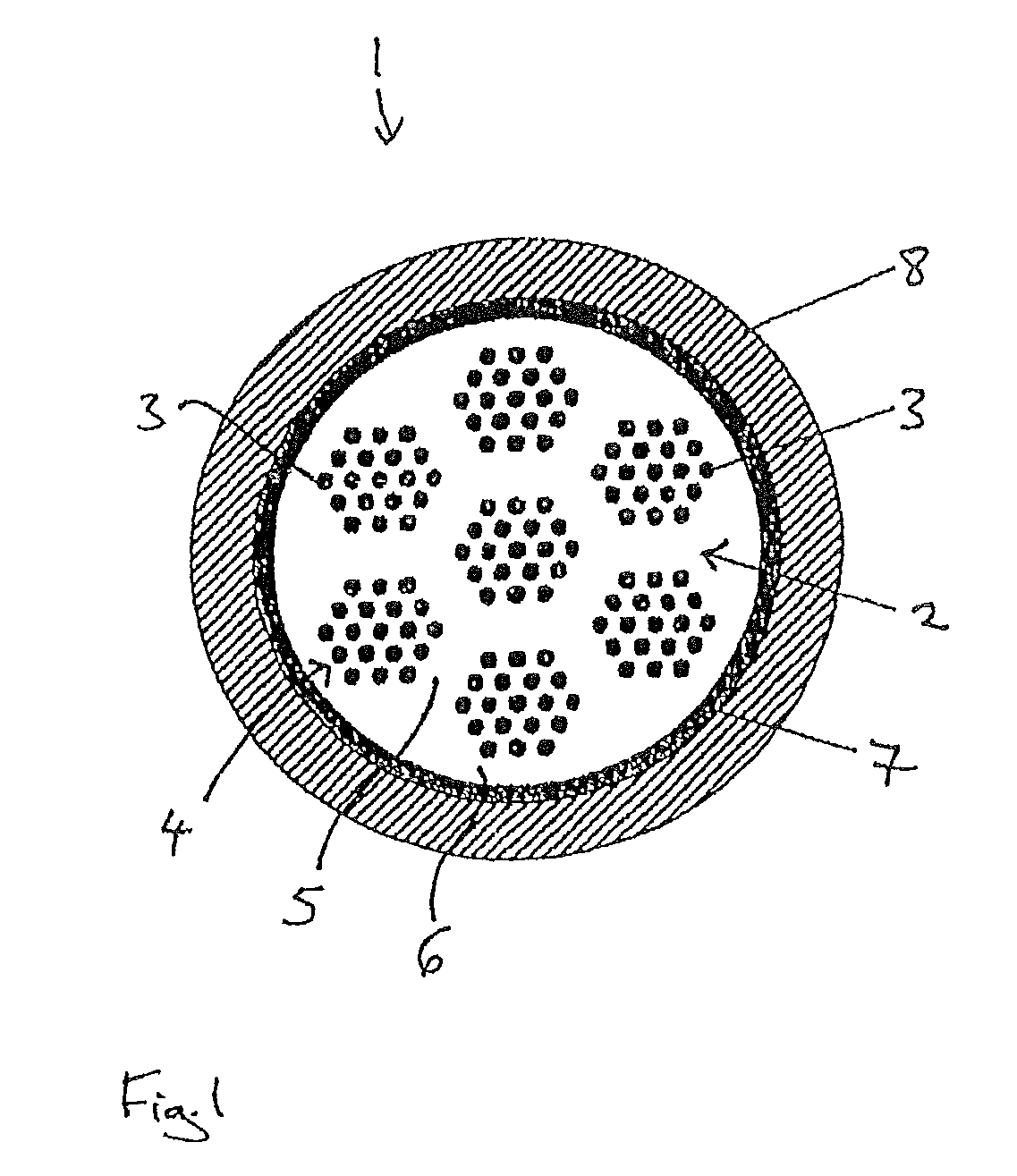
[0041]In this exemplary embodiment, at least a portion of the inner area of the first casing surrounds the respective filaments made of MgB2. The inner area may be comprised of one single area that continuously surrounds the filaments. Alternatively, the inner area may feature several subareas that are separated from one another. In the first exemplary embodiment the outer area of the first casing may include separate areas between the filaments and the inner area may consist of one single area. In a second exemplary embodiment, several ring-shaped inner areas are surrounded by ring-shaped outer areas.

[0...


PUM

PropertyMeasurementUnit
transition temperatureaaaaaaaaaa
Tcaaaaaaaaaa
Tcaaaaaaaaaa

Abstract

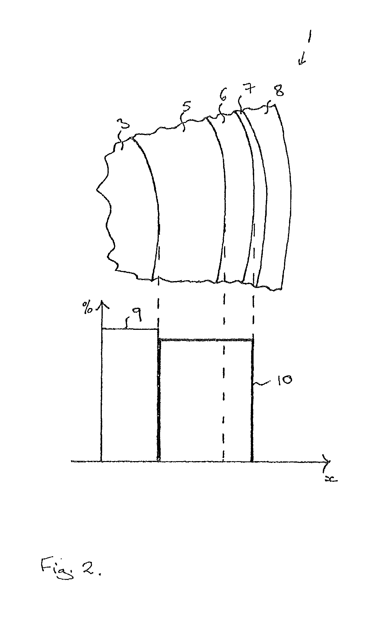
Disclosed herein are superconducting composites, and preliminary products therefor, having a core comprising a superconducting phase, a first casing surrounding the core, and having an inner area abutting the core and having a first magnesium concentration and an outer area having a second magnesium concentration greater than the first magnesium concentration, wherein the second magnesium concentration is, on average, between 5 and 40 atomic percent. Desirably, the superconducting phase comprises a MgB2 phase. This arrangement allows for methods for producing the composites that reduce or eliminate subjecting the superconducting phase to mechanical stresses.

Description

[0001]This application claims benefit of the filing date of DE 10 2008 049 672.3, filed Sep. 30, 2008, the entire contents of which are incorporated herein by reference.BACKGROUND[0002]1. Field[0003]Disclosed herein are to a superconducting composite, a preliminary product of a superconducting composite and method for producing same.[0004]2. Description of Related Art[0005]Various types of superconductors that can be produced on a large scale are known. NbTi alloys and intermetallic Nb3Sn compounds exhibit a transition temperature Tc of less than 20 K and can be produced in large strands by means of classic shaping methods such as extruding, thermoforming, or rolling. However, the low transition temperature leads to high equipment and cooling costs.[0006]Superconducting copper oxide-based compounds, e.g. YBCO (Tc approximately 92 K), Bi-2212 and Bi-2223 with a transition temperature of approximately 110 K and T1-2223 (Tc approximately 125 K) are also known. These superconductors are...

Claims


Application Information

Patent Timeline
Patent Type & Authority Patents(United States)
IPC IPC(8): H01F6/00H01B12/00H01L39/00H10N60/20H10N60/00H10N60/01
CPCH01L39/141H01L39/2487Y10T29/49014H10N60/202H10N60/0856
Inventor SCHLENGA, KLAUSSZULCZYK, ANDREAS
Owner BRUKER EAS
Learn More