Method and device for an actuator motor including a fan brake device

a technology of actuator motor and fan brake, which is applied in ventilation systems, heating types, valve housings, etc., can solve the problems of water valve closing, gear train damage, and inertia that is built up during back drive, and achieve the effect of reducing the rotating speed of the damper pla

Active Publication Date: 2012-12-04
HANSON CORP
View PDF9 Cites 2 Cited by
  • Summary
  • Abstract
  • Description
  • Claims
  • Application Information

AI Technical Summary

Benefits of technology

[0007]In a specific embodiment, the present invention provides for a damper actuator apparatus that includes a substantially sealed housing unit, and a drive motor configured within the sealed housing unit. As an example, the sealed housing unit can be maintained to prevent environmental entities such as dust particles, moisture, and other forms of contamination from entering into and severely damaging electronic elements within the housing. Although it is not required that the housing is perfectly and completely sealed in some embodiment, the term “sealed” should be construed by ordinary meaning according to one of ordinary skill in the art. The drive motor includes a drive member configured to be rotatable about an axial direction, and the drive member has a first end and a second end, which may be at the outermost portion or slightly within the outer most portion. The damper actuator apparatus also includes a drive device (e.g., electric motor, electric motor and gearing) and a spring device, e.g., coil, elastic member, which can be characterized by a spring constant and displacement or the like. The drive device is coupled to the motor via the drive member, the drive device being configured to be driven in a first direction about the axial direction by the motor, whereas the spring device is coupled to the drive device, the spring device being configured to apply force to the drive device such that the drive device rotates in a return direction opposite (which may be counter rotational) to the first direction. The damper actuator apparatus further includes a fan device coupled to the drive device, the fan device being configured to reduce a velocity of the drive device during a portion of time when the drive device rotates in the return direction opposite of the first direction. In an embodiment, the sealed housing unit is substantially free from dust particles. In other embodiments, the sealed housing unit can be completely sealed. The sealed housing unit can also include a lower housing member coupled to an upper housing member. Alternatively, the housing unit can be a single piece or multiple pieces according to a specific embodiment. In an embodiment, the upper housing member also includes a plurality of baffles to increase air resistance.
[0012]In another specific embodiment, the invention provides for a damper assembly that includes a damper plate having a first position and a second position, the damper plate including a damper shaft, and an actuator apparatus coupled to the damper shaft, the actuator apparatus being configured to drive the damper plate between at least the first position and the second position. In an embodiment, the actuator apparatus includes a fan device, the fan device being configured to reduce the rotating speed of the damper plate when the actuator apparatus drives the damper plate from the second position to the first position. The valve actuator motor device can further include a substantially sealed housing member, a drive motor within the sealed housing member, a drive device coupled to the motor and configured to be driven in a first direction by the motor, and a spring device coupled to the drive device and configured to drive the drive device and the motor in a return direction opposite to the first direction.

Problems solved by technology

Conversely, apply power to normally closed dampers causes them to open.
The speeds generated during back driving can often greatly exceed the speeds the motor travels when energized.
The inertia that is built up during back drive can damage the gear train after repeated impacts.
In water delivery systems using conventional valve actuators, such high speed back drive causes water valves to close quickly, and the sudden interruption in water flow often causes a loud noise commonly known as water hammer.
Such conventional braking devices are often complex and expensive and are often susceptible to reliability problems.

Method used


Image

  • Method and device for an actuator motor including a fan brake device
  • Method and device for an actuator motor including a fan brake device
  • Method and device for an actuator motor including a fan brake device

Examples


Embodiment Construction

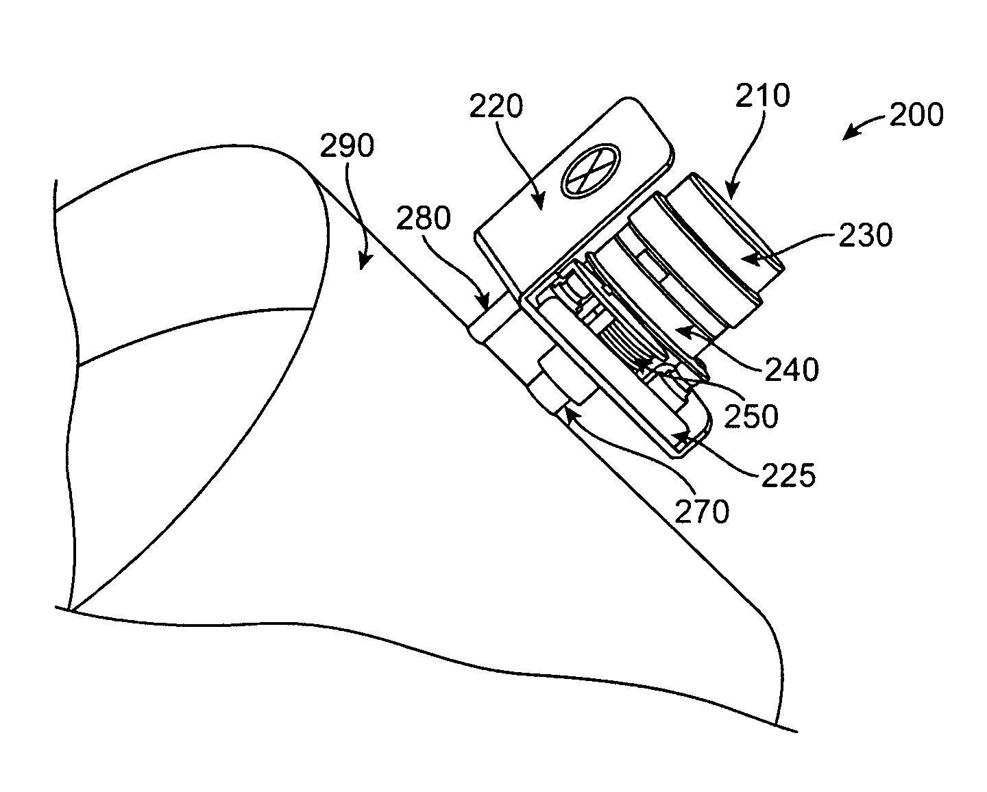
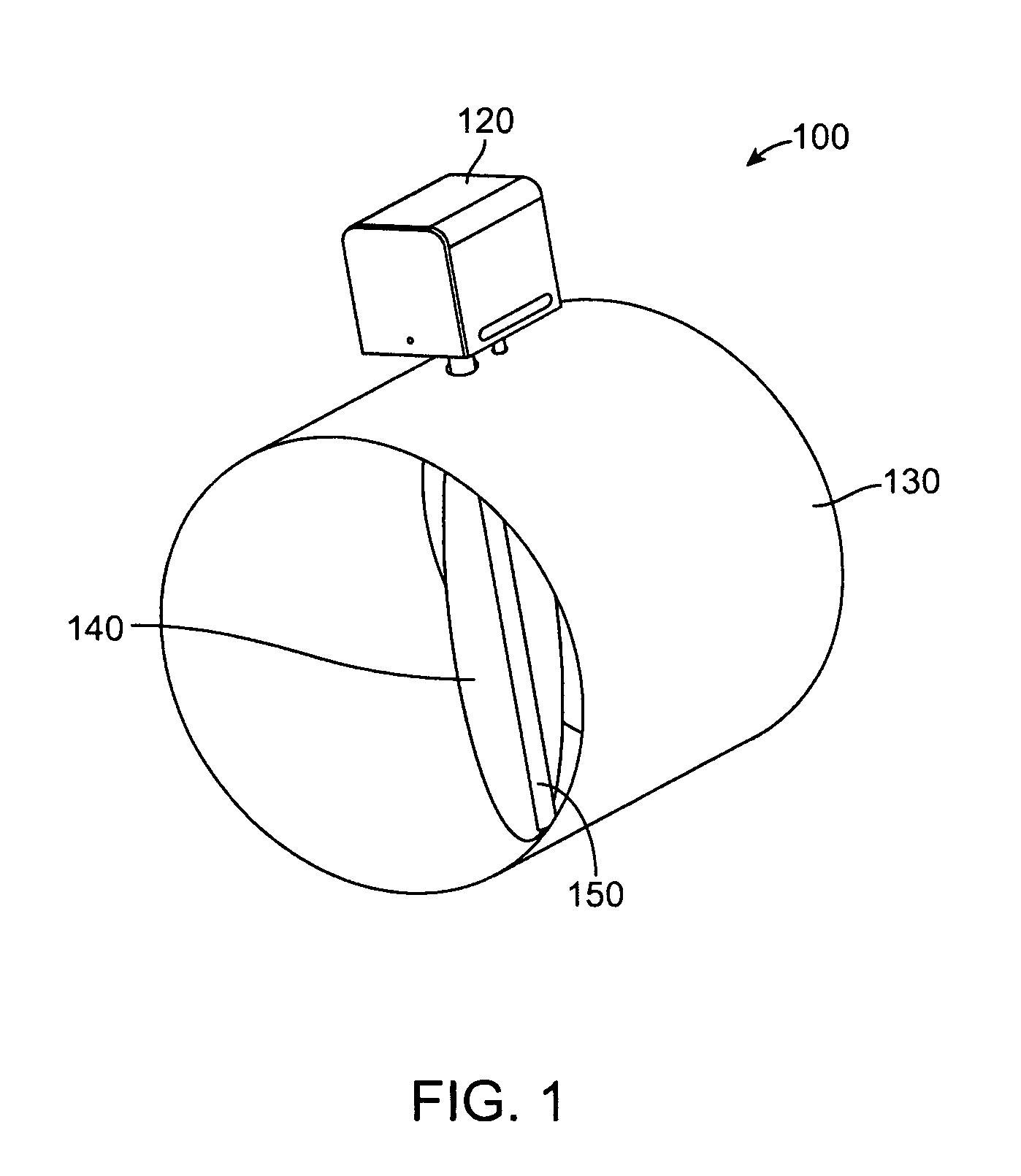
[0022]The present invention provides techniques directed generally to air and fluid delivery systems. More particularly, the present invention provides a method and device for an improved motor actuator for controlling dampers or valves used in air or fluid delivery systems. Merely by way of example, the present invention provides techniques for a damper actuator motor including a fan brake which is configured to provide a braking force when the motor actuator is back driven. But it would be recognized that the invention has a much broader range of applicability. For example, the invention can be applied to motor actuators used to control valves in various gas or fluid delivery systems. The invention can also be used to reduce water hammer in water delivery systems.

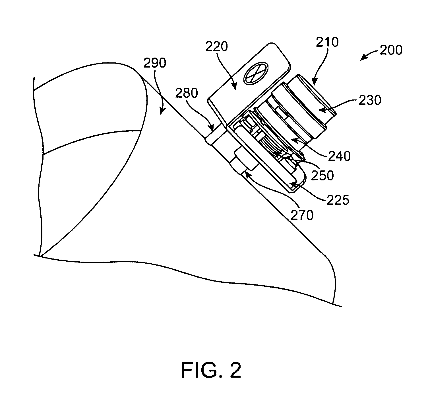
[0023]According to an embodiment of the present invention, a fan brake device is secured to the motor rotor shaft of an actuator motor such that when the motor is powered on, the force generated by the fan blades is not s...


PUM


Abstract

A damper actuator motor device includes a fan brake device which is secured to a motor rotor shaft and is configured to reduce motor rotation speed in a preferential direction. Preferably, the fan brake device has an asymmetric configuration, and is adapted to gather air radially in an enclosed cavity and discharge it axially in one direction. The fan device preferably is adapted to project a size that takes up more than half of the space of the cavity. When the motor is back driven, the fan brake device causes differentially pressure and air resistance in a confined area, producing a drag and braking force that increases with motor speed. The invention can be applied to motor actuators used to control air dampers and other valves in gas or fluid delivery systems. The invention can also be used to reduce water hammer in water delivery systems.

Description

BACKGROUND OF THE INVENTION[0001]The present invention is directed generally to air and fluid delivery systems. More particularly, the present invention provides a method and device for an improved motor actuator for controlling dampers or valves used in air or fluid delivery systems. Merely by way of example, the present invention provides techniques for an air duct damper actuator motor including a fan brake configured to produce a braking force when the motor actuator is back driven. But it would be recognized that the invention has a much broader range of applicability. For example the invention can be applied to motor actuators used to control valves in various gas or fluid delivery systems. The invention can also be used to reduce water hammer in water delivery system.[0002]In an HVAC (Heating, Ventilation and Air-Conditioning) system, sometimes referred to as climate control system, extensive ductwork throughout a building is often used to control temperature and humidity of ...

Claims


Application Information

Patent Timeline
Patent Type & Authority Patents(United States)
IPC IPC(8): F16K31/02
CPCA62C35/68F16K1/221F16K31/041F16K47/023F24F13/1426F24F2011/0095F24F2013/1466F24F11/33
Inventor DREHER, LINCOLN J.
Owner HANSON CORP
Why Eureka
Try Eureka