Method for use of a compression stabilized prosthetic socket interface

Active Publication Date: 2012-12-04
ALLEY RANDALL D MR
View PDF14 Cites 50 Cited by
  • Summary
  • Abstract
  • Description
  • Claims
  • Application Information

AI Technical Summary

Benefits of technology

[0058]It is a further object of various embodiments of the present invention to provide bars with center sections that telesco

Problems solved by technology

There are deep channels formed in the positive model, which are a cause of excessive thickness in these areas when conventional lamination procedures are used.
From the inv

Method used


Image

  • Method for use of a compression stabilized prosthetic socket interface
  • Method for use of a compression stabilized prosthetic socket interface
  • Method for use of a compression stabilized prosthetic socket interface

Examples


Embodiment Construction

)

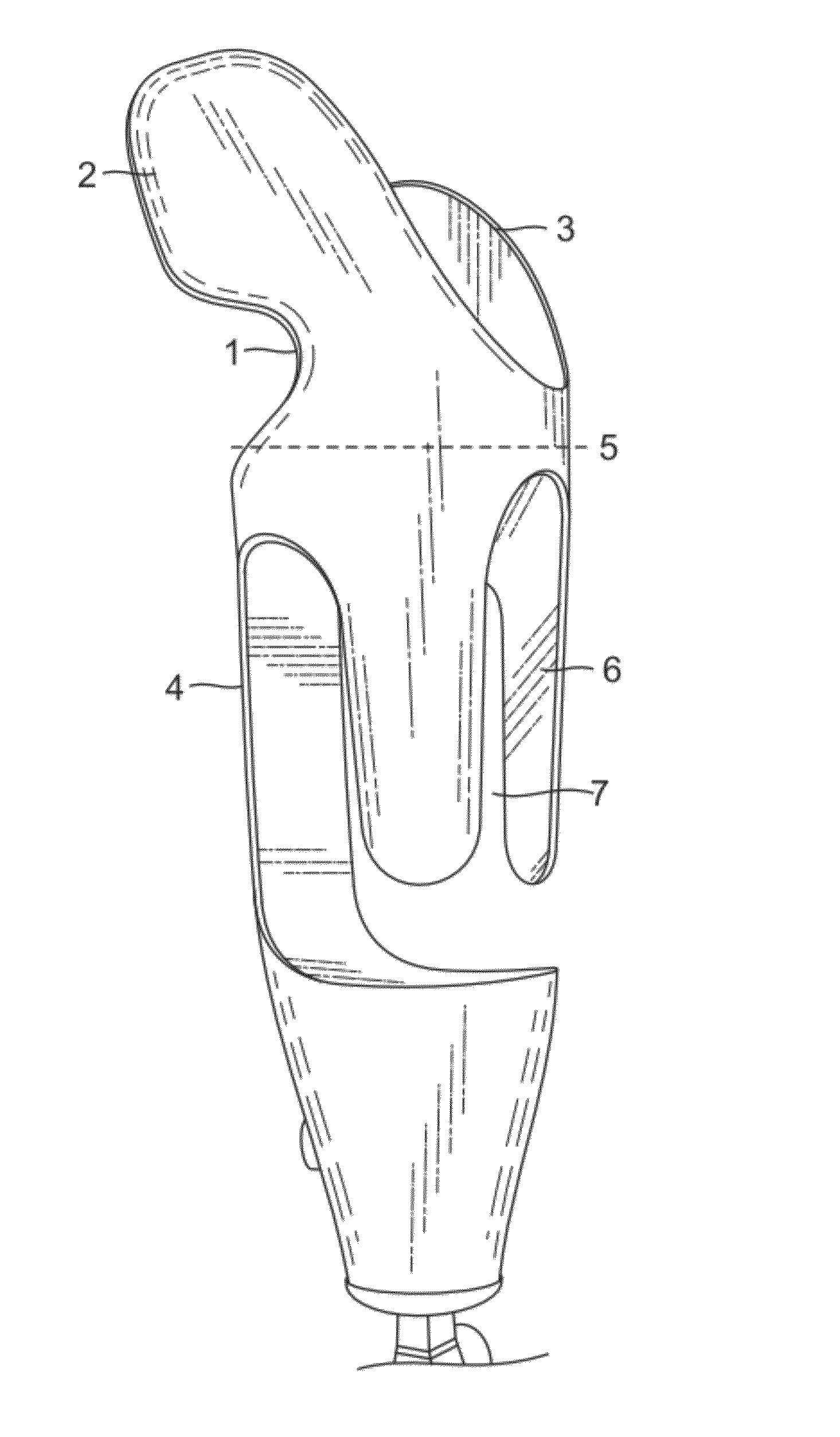
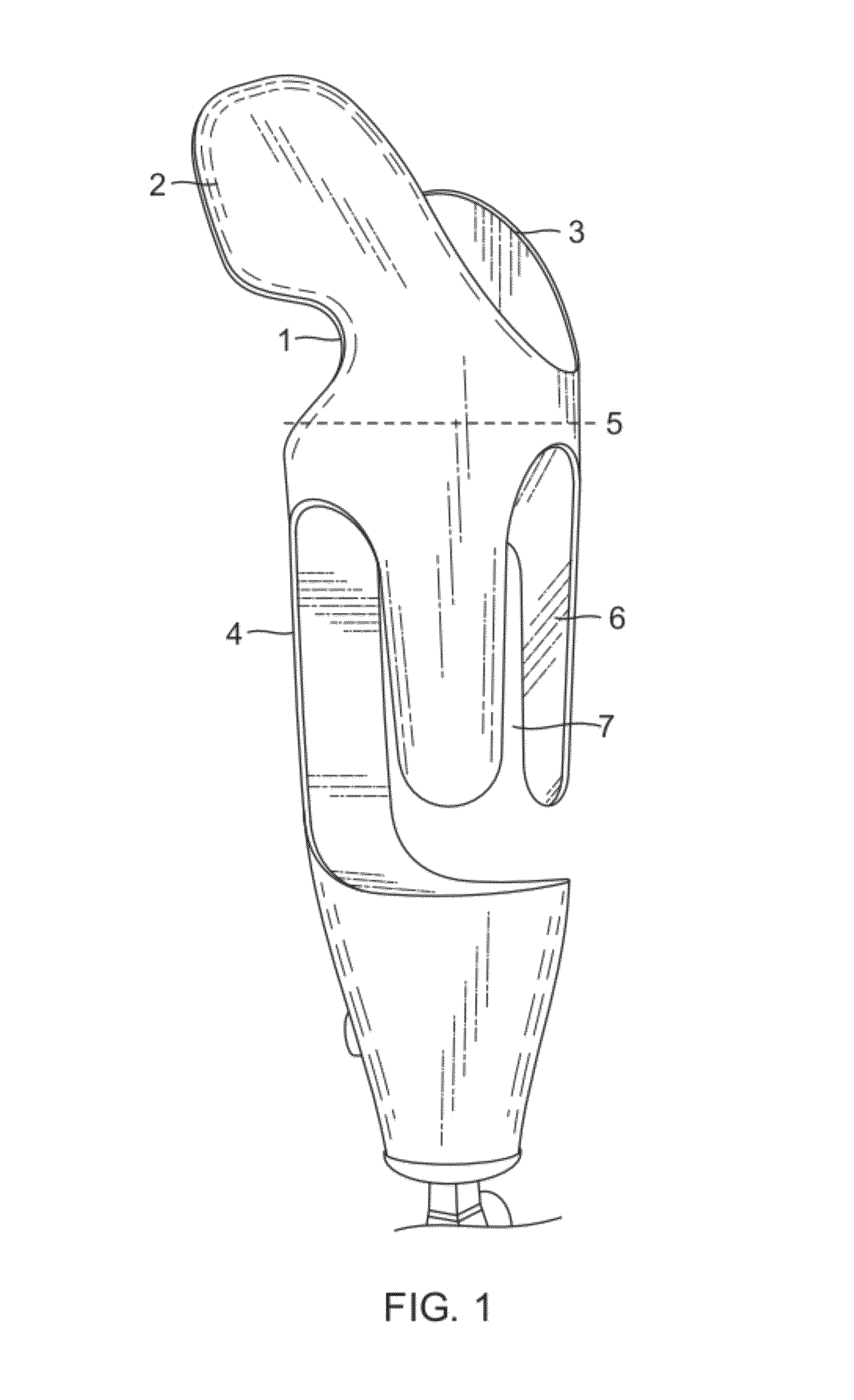
[0071]As shown in FIG. 1, a the transhumeral open-cage interface embodiment, there is an upper portion 1, which has both an anterior stabilizer 2 and a posterior stabilizer 3 and which extends in a proximal (in this case toward a patient's shoulder) and medial (toward a patient's midline) direction from a lower portion 4 to stabilize the interface on a patient's body. Although stabilizers 2 and 3 are not required, they are recommended to impart or enhance rotational stability. The lower portion 4 (below line 5) has an open-cage structure. Dashed horizontal line 5 demarcates the upper and lower portions. The lower portion 4 of this open-cage embodiment has multiple, e.g. three or four struts 6, which look like fingers that extend along the long axis of the residual limb and are designed to partially encompass the residual limb, allowing soft tissue to flow through windows 7.

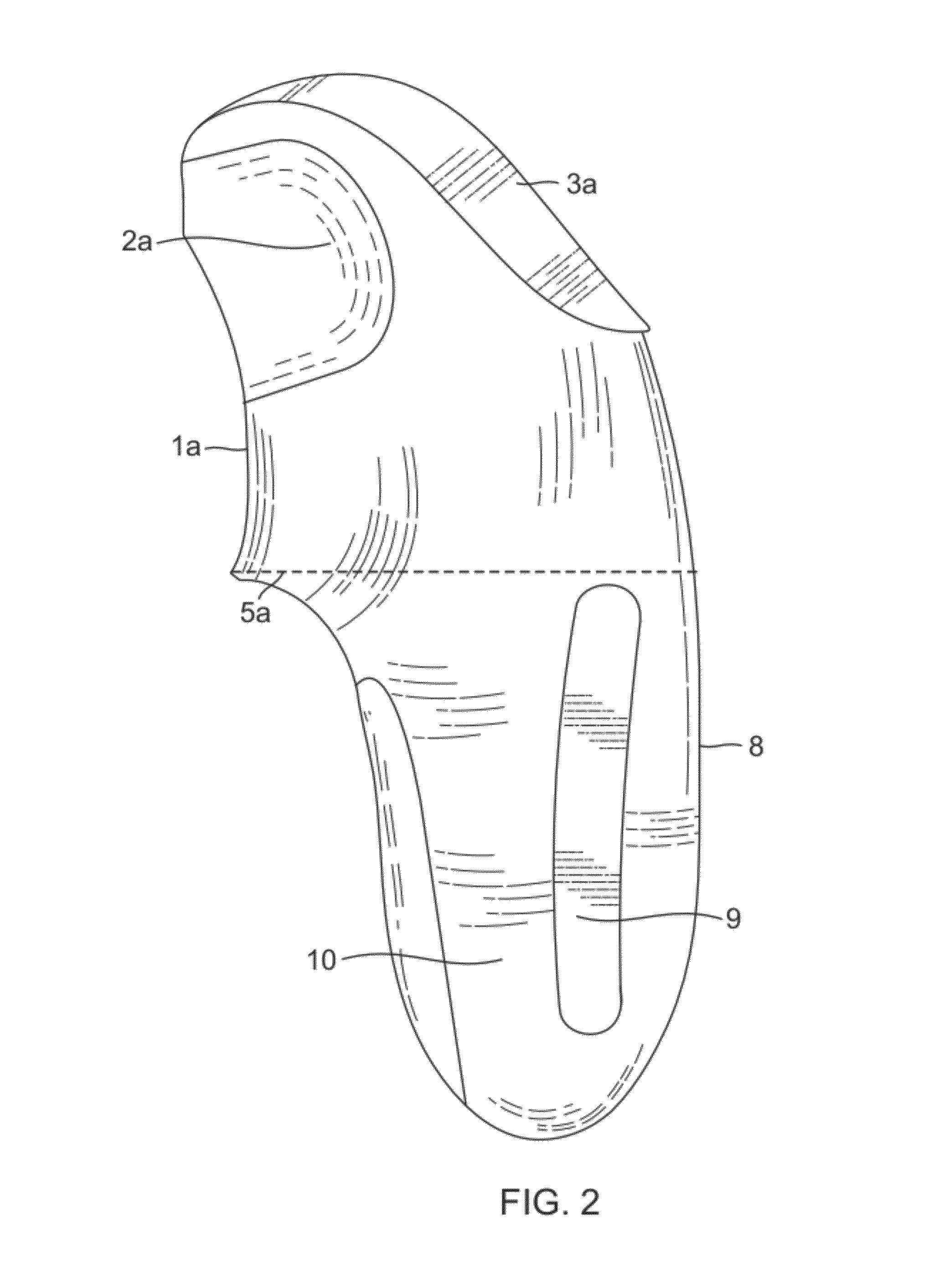
[0072]As shown in FIG. 2, a transhumeral solid-body interface embodiment, there is an upper portion 1a, which ...


PUM


Abstract

A compression stabilized prosthetic socket for a patient having an amputated limb and a remaining portion includes a first socket portion for contacting a patient's remaining portion of a limb, and a second socket portion for attachment of a prosthetic device. The first socket portion has compression portions having a radius for compressing portions of the patient's remaining portion of a limb, and relief portions receiving any portions of the patient's remaining limb which bulge upon the compression applied by the compression portions. The relief portions may be formed as openings or as enlarged radius portions.

Description

CROSS REFERENCE TO RELATED APPLICATION(S)[0001]This application is a continuation-in-part of, and claims the benefit of priority from U.S. patent application Ser. No. 12 / 792,728, filed Jun. 2, 2010 which in turn is a continuation-in-part of, and claims the benefit of priority from U.S. patent application Ser. No. 12 / 380,861, filed Mar. 4, 2009 now abandoned, which in turn claims benefit of U.S. Provisional Patent Application No. 61 / 068,263 filed Mar. 4, 2008, all three of which such applications are incorporated by reference herein.BACKGROUND OF THE INVENTION[0002]1. Field of the Invention[0003]The present invention relates to the prosthetic limbs worn by upper or lower limb amputees and in particular to the portion of a limb prosthesis that is in direct contact with the user's skin.[0004]2. Description of the Related Art[0005]Definitions of Terms[0006]Socket—is that part of a prosthesis in direct contact with the user's skin. The word Socket usually implies a traditional socket tha...

Claims


Application Information

Patent Timeline
IPC IPC(8): A61F2/78
CPCA61F2/76A61F2/80A61F2/78A61F2002/7818B33Y80/00A61B5/00A61B5/107A61F2/5046A61F2002/5049A61F2002/5053A61F2002/5056
Inventor ALLEY, RANDALL D.WILLIAMS, III, T. WALLEY
Owner ALLEY RANDALL D MR
Why Eureka
Try Eureka