Table saw with reset mechanism

a technology of table saw and reset mechanism, which is applied in the direction of band saws, metal sawing accessories, manufacturing tools, etc., can solve the problems of affecting the use of the table saw, the blade guard is typically not compatible with the dado blade, and the table saw is very heavy and relatively immobil

Active Publication Date: 2012-12-11
CREDO TECH CORP +1
View PDF87 Cites 31 Cited by
  • Summary
  • Abstract
  • Description
  • Claims
  • Application Information

AI Technical Summary

Benefits of technology

[0008]In accordance with one embodiment, a power tool includes a work-piece support surface, a swing arm movable along a swing arm path between an upper first swing arm position and a lower second swing arm position, a latch hold mechanism movable between a first latch hold position adjacent to the swing path and a second latch hold position whereat at least a portion of the latch hold mechanism is within the swing path, an actuator configured to force the swing arm assembly away from the first swing arm position and toward the second swing arm position, a swing arm reset configured to pivot the swing arm from the second swing arm position to the first swing arm position in response to a first user applied force, a latch hold reset configured to pivot the latch hold mechanism from the second latch hold position to the first latch hold position in response to a second user applied force, and a control system configured to control the actuator.
[0009]In another embodiment, a table saw includes a work-piece support surface, a blade support shaft automatically retractable along a retraction path from a first position to a second position in response to a sensed condition, wherein the second po

Problems solved by technology

Some table saws such as cabinet table saws are very heavy and relatively immobile.
Accordingly, severe injury such as severed digits and deep lacerations can occur almost instantaneously.
While blade guards are effective to prevent some injuries, the blade guards can be removed by a user either for convenience of using the table saw or because the blade guard is not compatible for use with a particular shaping device.
By way of example, a blade guard is typically not compatible with a dado blade and must

Method used


Image

  • Table saw with reset mechanism
  • Table saw with reset mechanism
  • Table saw with reset mechanism

Examples


Embodiment Construction

[0042]While the power tools described herein are susceptible to various modifications and alternative forms, specific embodiments thereof have been shown by way of example in the drawings and will herein be described in detail. It should be understood, however, that there is no intent to limit the power tools to the particular forms disclosed. On the contrary, the intention is to cover all combinations of features, modifications, equivalents, and alternatives falling within the spirit and scope of the invention as defined by the appended claims.

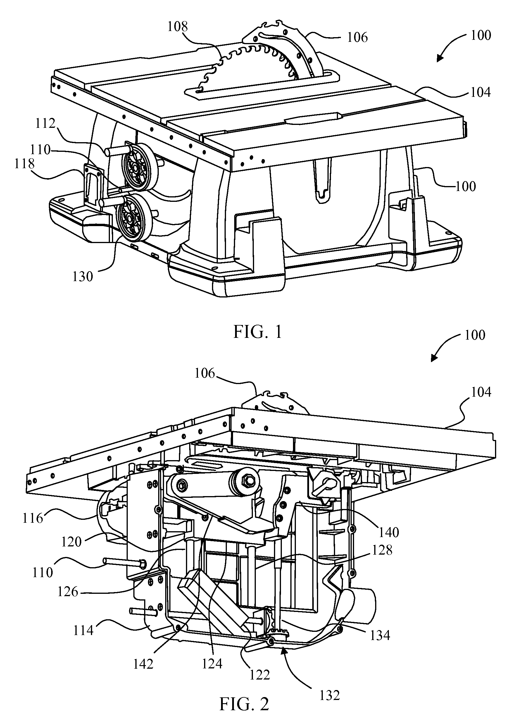
[0043]Referring to FIG. 1, a table saw 100 is shown. The table saw 100 includes a base housing 102 and a work-piece support surface 104. A splitter 106 is positioned adjacent to a blade 108 which extends from within the base housing 102 to above the work-piece support surface 104. A blade guard (not shown) may be attached to the splitter 106. An angle indicator 110 indicates the angle of the blade 108 with respect to the work-piece support su...


PUM


Abstract

A power tool in one embodiment includes a swing arm movable along a swing arm path between an upper first swing arm position and a lower second swing arm position, a latch hold mechanism movable between a first latch hold position adjacent to the swing path and a second latch hold position whereat at least a portion of the latch hold mechanism is within the swing path, an actuator configured to force the swing arm assembly away from the first swing arm position and toward the second swing arm position, a swing arm reset configured to pivot the swing arm from the second swing arm position to the first swing arm position, a latch hold reset configured to pivot the latch hold mechanism from the second latch hold position to the first latch hold position, and a control system configured to control the actuator.

Description

[0001]Cross-reference is made to U.S. patent application Ser. No. 12 / 547,818 entitled “Table Saw with Actuator Module” by Mehta et al., which was filed on Aug. 26, 2009; U.S. patent application Ser. No. 12 / 547,859 entitled “Table Saw with Dust Shield” by Chung, which was filed on Aug. 26, 2009; U.S. patent application Ser. No. 12 / 547,912 entitled “Table Saw with Positive Locking Mechanism” by Chung et al., which was filed on Aug. 26, 2009; U.S. patent application Ser. No. 12 / 547,977 entitled “Table Saw with Belt Stop” by Chung, which was filed on Aug. 26, 2009; U.S. patent application Ser. No. 12 / 548,035 entitled “Table Saw with Alignment Plate” by Chung et al., which was filed on Aug. 26, 2009; U.S. patent application Ser. No. 12 / 548,156 entitled “Table Saw with Swing Arm Support” by Chung et al., which was filed on Aug. 26, 2009; U.S. patent application Ser. No. 12 / 548,201 entitled “Table Saw with Mechanical Fuse” by Oberheim, which was filed on Aug. 26, 2009; U.S. patent applicat...

Claims


Application Information

Patent Timeline
IPC IPC(8): B23D45/06B26D7/22B27G19/02
CPCB23D45/067B23D47/08B23D59/002B27G19/02B23D45/061Y10T83/773Y10T83/089Y10T83/081Y10T83/8749
Inventor GROTH, BRADY J.MEHTA, AMIT K.DOUMANI, ROBERT S.
Owner CREDO TECH CORP
Why Eureka
Try Eureka