
Hoist with overspeed protection

a technology of overspeed protection and hoist, which is applied in the direction of motor/generator/converter stopper, dynamo-electric converter control, hoisting equipment, etc., can solve the problems of increasing the chance of damage or injury to the operator, the load, or even the structure to which the hoist is attached, and the chance of significant time passing, so as to achieve the effect of a larger margin of error

Inactive Publication Date: 2012-12-11
WENGER CORPORATION
View PDF10 Cites 3 Cited by
  • Summary
  • Abstract
  • Description
  • Claims
  • Application Information

AI Technical Summary

Benefits of technology

"The present invention improves upon conventional hoist braking systems by using encoders to compare the rotational velocities of different parts of the hoist. This allows for quicker detection of overspeed conditions and prevents damage or injury to operators, load, or structure. The invention also includes a controller module that can activate the brakes to prevent accidents and reduce damage or injury. The invention can be used in various hoist systems, such as those with clutches or other rotational couplings."

Problems solved by technology

Furthermore, when the operating speeds are relatively slow, there is a larger margin for error because the hoist and load are always travelling at a relatively slow speed.
The shock loading associated with stopping the load from a higher speed increases the chance of damage or injury to the operators, the load, or even to the structure to which the hoist is attached.
Moreover, the fact that the mechanical brake waits for the overspeed to reach the trigger speed means that considerable time may pass and considerable unwanted load distance, load velocity and load acceleration may need to accrue before the trigger speed is reached.
Conventional electrical brakes may be subject to similar performance issues, especially when there is merely a single fixed maximum speed set point (see DEFINITIONS section) for each electrical brake(s) present in the braking sub-system(s).

Method used


Image

  • Hoist with overspeed protection
  • Hoist with overspeed protection
  • Hoist with overspeed protection

Examples


Embodiment Construction

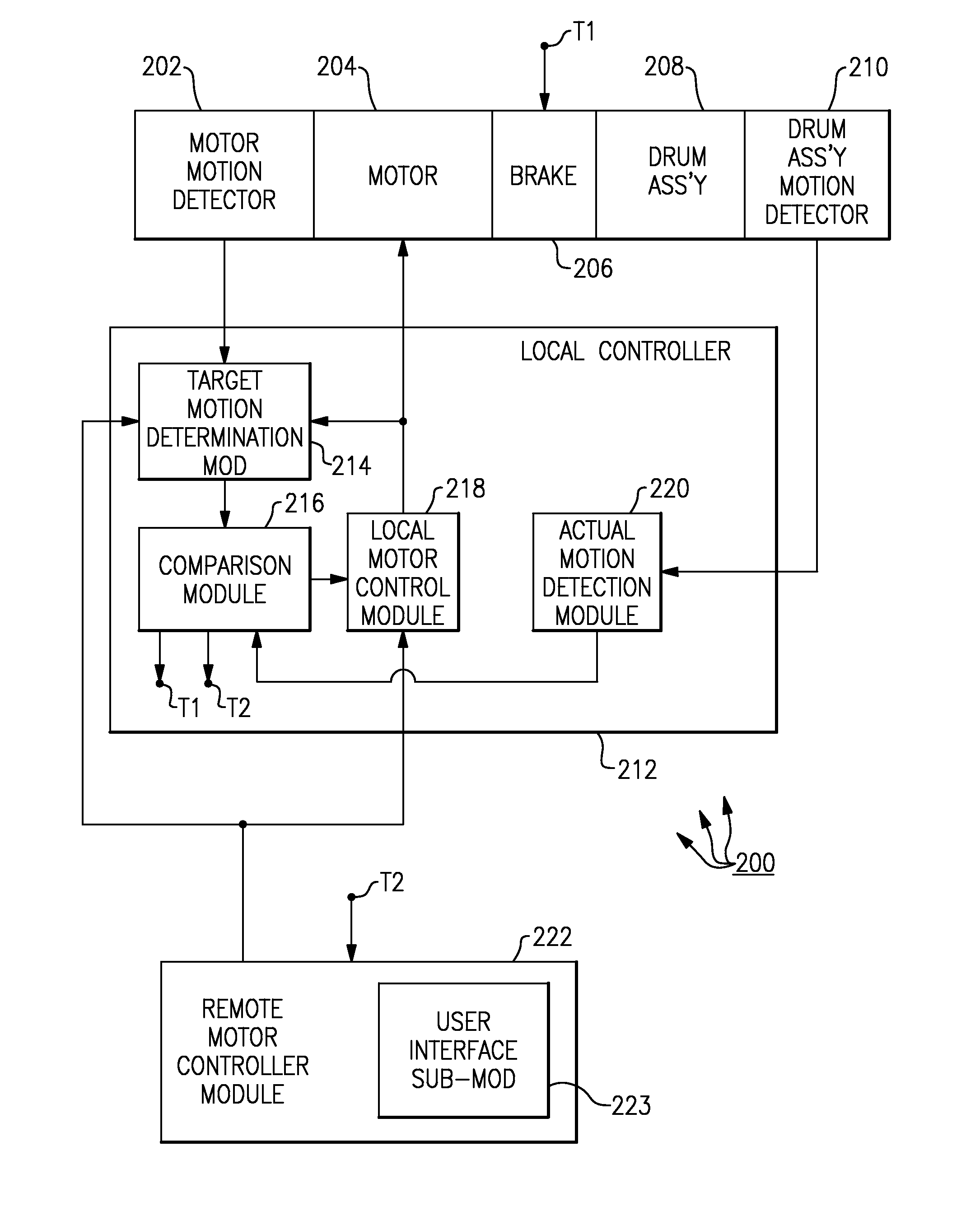
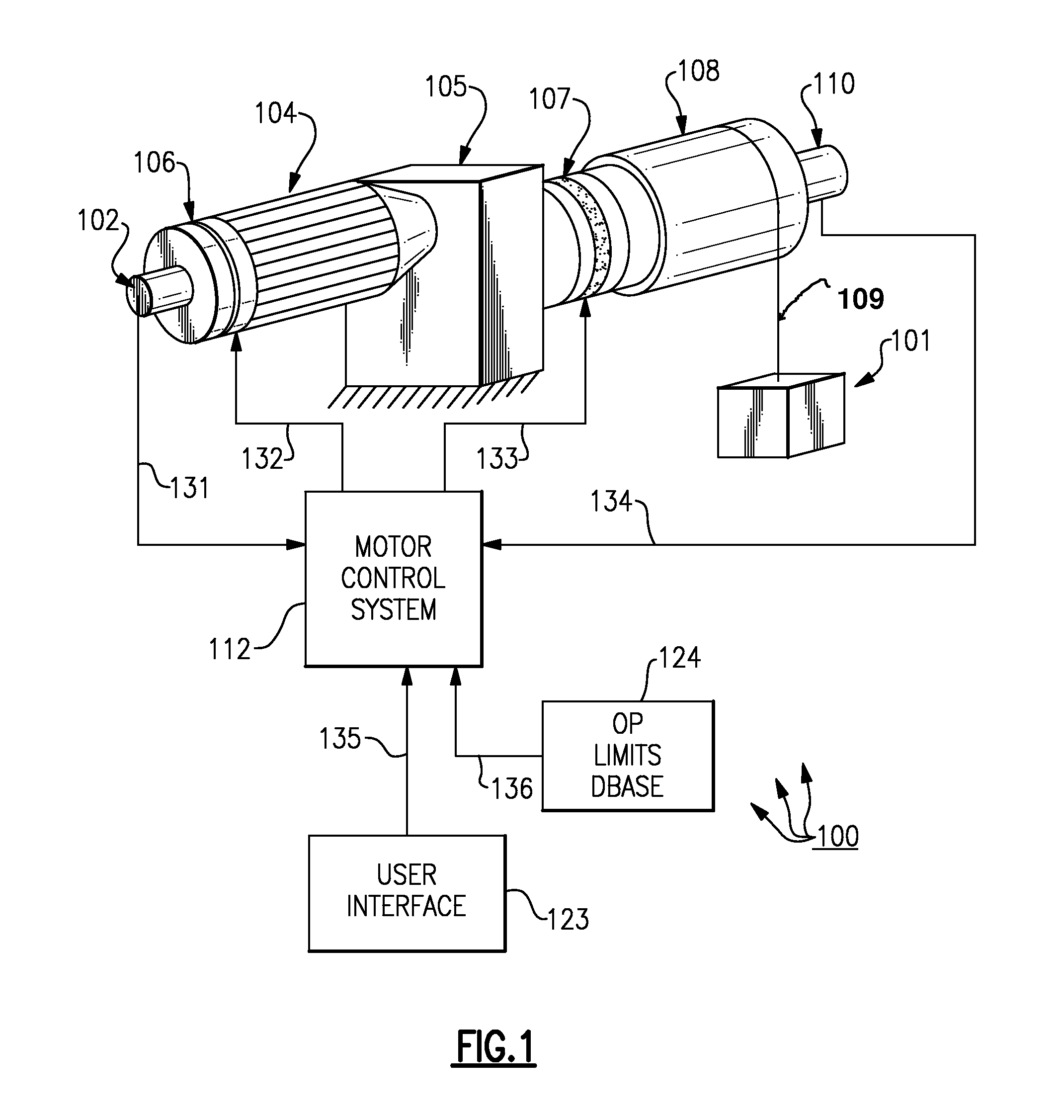
[0026]FIG. 1 shows hoist system 100 including: load 101; first rotary encoder 102; motor 104; reducer 105; motor brake 106; drum brake 107; drum 108; cable 109; second rotary encoder 110; motor control system 112; user interface 123; and operational limits database 124. In operation, a user interactively uses user interface 123 to direct the motor control system to control the motor to rotationally move the drum. The rotational motion of the drum winds / unwinds a cable to thereby move the load in a desired manner. For example, a speed setpoint command signal 135 may be sent from the user interface to the motor control system to set a speed for turning the motor and thereby turning the drum (through the reducer) to raise or lower the load at a desired speed. Alternatively, desired control of the motor by the motor controller may be partially, or wholly, pre-programmed and / or automatic. In all cases, the motor control system sends appropriate power and / or control signals 132 to the mot...


PUM


Abstract

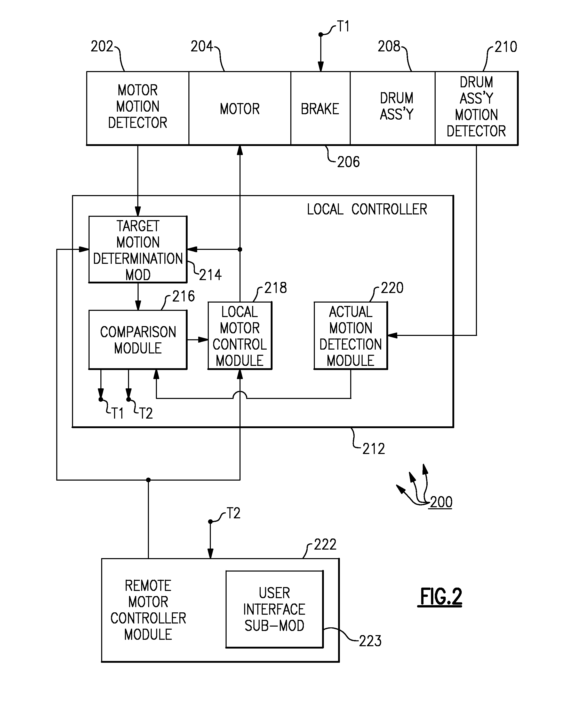
A hoist system with an overspeed detection sub-system for detecting overspeed by comparing an actual drum assembly speed with a target value. For example, the rotation of a motor may be determined by a first rotary encoder and the rotation of a drum may be determined by a second rotary encoder. The output of the first rotary encoder (the basis of a target value) is compared with the output of the second rotary encoder (corresponding to actual motion of the drum). If the difference between the target value and the actual motion is too large, then a problem, such as a broken hoist hardware component may exist, and appropriate remedial action is taken, such as braking the motor and / or the drum.

Description

RELATED APPLICATION[0001]The present application claims priority to U.S. provisional patent application No. 61 / 160,849, filed on Mar. 17, 2209; all of the foregoing patent-related document(s) are hereby incorporated by reference herein in their respective entirety(ies).BACKGROUND OF THE INVENTION[0002]1. Field of the Invention[0003]The present invention relates to powered hoists (see DEFINITIONS section) and more particularly to powered hoists for theatrical applications.[0004]2. Description of the Related Art[0005]Hoists are conventional, and the use of powered hoists in theatres to raise, lower and otherwise move lighting and scenery and the like is also conventional. In conventional hoist systems, a widely employed mechanical overspeed brake uses a centrifugal device to detect excessive rotational speed and to deploy linkages to engage a disk or drum brake. This type of brake is sometimes referred to herein as a “mechanical brake.” In a conventional a mechanical brake, the rotati...

Claims


Application Information

Patent Timeline
Patent Type & Authority Patents(United States)
IPC IPC(8): B66D1/48
CPCB66D1/12B66D1/14B66D1/54B66D5/30
Inventor ESCHELBACHER, LAWRENCE L.SVITAVSKY, PETER V.
Owner WENGER CORPORATION
Learn More