Hyper temporal LIDAR with dynamic laser control using laser energy and mirror motion models

a lidar and dynamic technology, applied in the field of lidar systems, can solve the problems of putting pressure on the operational capabilities of the laser source employed, affecting the energy characteristics of the source, and being particularly acu

Active Publication Date: 2022-09-20
AEYE INC
View PDF314 Cites 4 Cited by
  • Summary
  • Abstract
  • Description
  • Claims
  • Application Information

AI Technical Summary

Benefits of technology

The patent text describes a technology that uses a laser energy model to predict the energy levels of laser pulses in a lidar transmitter. This allows the system to determine the timing schedule for each laser pulse based on the energy levels predicted. By using this model, the system can reliably ensure that each laser pulse has enough energy to meet its operational needs. This technology also allows the system to predict where the scanning mirror is aimed in the field of view over time, which helps ensure that laser pulses are targeted at the right range points. This results in a lidar system that can operate at high rates with high timing and spatial precision.

Problems solved by technology

However, as the firing rate for the lidar transmitter increases, this places pressure on the operational capabilities of the laser source employed by the lidar transmitter because the laser source will need re-charging time.
This issue becomes particularly acute in situations where the lidar transmitter has a variable firing rate.
Such laser sources have energy characteristics that are heavily impacted by time and the firing rate of the laser source.

Method used


Image

  • Hyper temporal LIDAR with dynamic laser control using laser energy and mirror motion models
  • Hyper temporal LIDAR with dynamic laser control using laser energy and mirror motion models
  • Hyper temporal LIDAR with dynamic laser control using laser energy and mirror motion models

Examples


Embodiment Construction

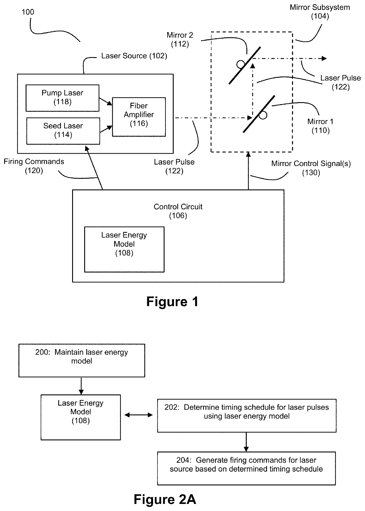
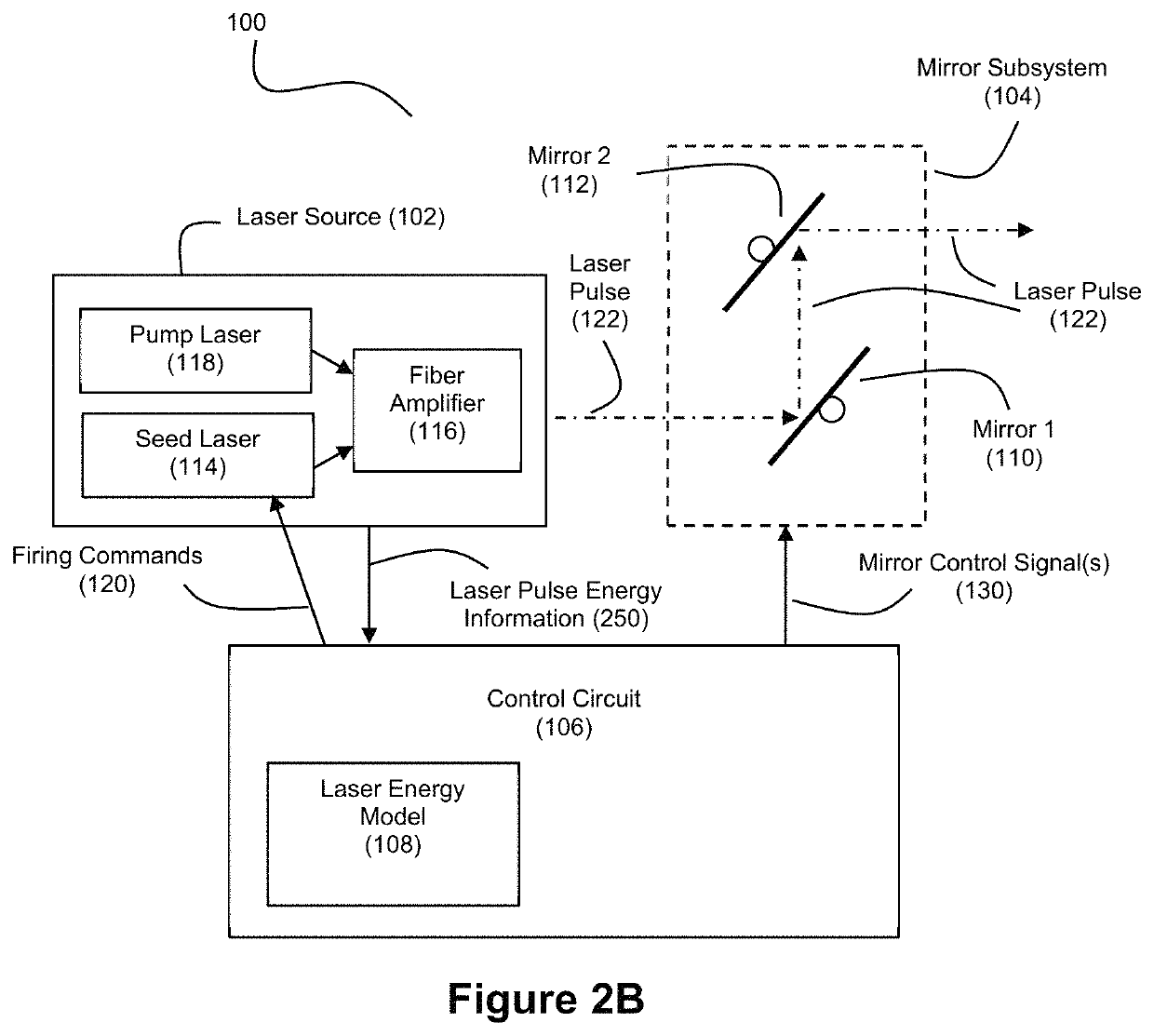
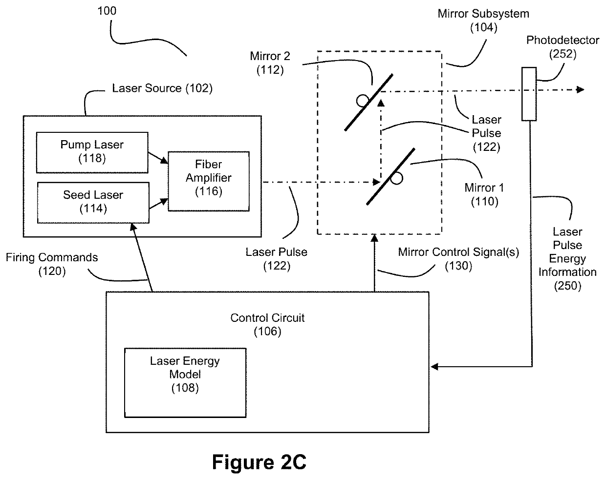
[0032]FIG. 1 shows an example embodiment of a lidar transmitter 100 that can be employed to support hyper temporal lidar. In an example embodiment, the lidar transmitter 100 can be deployed in a vehicle such as an automobile. However, it should be understood that the lidar transmitter 100 described herein need not be deployed in a vehicle. As used herein, “lidar”, which can also be referred to as “ladar”, refers to and encompasses any of light detection and ranging, laser radar, and laser detection and ranging. In the example of FIG. 1, the lidar transmitter 100 includes a laser source 102, a mirror subsystem 104, and a control circuit 106. Control circuit 106 uses a laser energy model 108 to govern the firing of laser pulses 122 by the laser source 102. Laser pulses 122 transmitted by the laser source 102 are sent into the environment via mirror subsystem 104 to target various range points in a field of view for the lidar transmitter 100. These laser pulses 122 can be interchangeab...


PUM


Abstract

A lidar system that includes a laser source and transmits laser pulses produced by the laser source toward range points in a field of view via a mirror that scans through a plurality of scan angles can use (1) a laser energy model to model the available energy in the laser source over time and (2) a mirror motion model to model motion of the mirror over time. Time slots for transmitting the targeted laser pulses can be identified using the mirror motion model, and a schedule for these pulses can be determined using energies predicted for the pulses at these time slots according to the laser energy model. Linking the model of mirror motion with the model of laser energy provides highly precise granularity when scheduling laser pulses targeted at specific range points in the field of view.

Description

CROSS-REFERENCE AND PRIORITY CLAIM TO RELATED PATENT APPLICATIONS[0001]This patent application claims priority to U.S. provisional patent application 63 / 166,475, filed Mar. 26, 2021, and entitled “Hyper Temporal Lidar with Dynamic Laser Control”, the entire disclosure of which is incorporated herein by reference.[0002]This patent application is related to (1) U.S. patent application Ser. No. 17 / 482,787, filed this same day, and entitled “Hyper Temporal Lidar with Dynamic Laser Control Using a Laser Energy Model”, (2) U.S. patent application Ser. No. 17 / 482,806, filed this same day, and entitled “Hyper Temporal Lidar with Dynamic Laser Control for Scan Line Shot Scheduling”, (3) U.S. patent application Ser. No. 17 / 482,811, filed this same day, and entitled “Hyper Temporal Lidar with Dynamic Laser Control Using Safety Models”, (4) U.S. patent application Ser. No. 17 / 482,820, filed this same day, and entitled “Hyper Temporal Lidar with Shot Scheduling for Variable Amplitude Scan Mirror...

Claims


Application Information

Patent Timeline
Patent Type & Authority Patents(United States)
IPC IPC(8): G01S7/481G01S7/484G01S17/10G01S17/931
CPCG01S7/4817G01S7/484G01S7/4814G01S17/10G01S17/931G01S17/42G01S17/89G01S7/4816
Inventor FERU, PHILIPPEDUSSAN, LUISBENSCOTER, JOELLIANG, ALEXPOLISHCHUK, IGORSTEINHARDT, ALLAN
Owner AEYE INC
Why Eureka
Try Eureka