Electric pump system

a technology of electric pump and hydraulic fluid, which is applied in the direction of pump control, gearing control, gearing elements, etc., can solve the problems of difficult to reliably ensure the hydraulic pressure of the hydraulic fluid, shock may occur in the vehicle, and the hydraulic pressure that is required to actuate the hydraulically-actuated device may not be guaranteed, so as to achieve reliable ensuring the hydraulic pressure and consumption less electricity

Active Publication Date: 2013-07-04
JTEKT CORP
View PDF2 Cites 11 Cited by
  • Summary
  • Abstract
  • Description
  • Claims
  • Application Information

AI Technical Summary

Benefits of technology

[0010]It is an object of the invention to provide an electric pump system that consumes less electricity while further reliably ensuring the hydraulic pressure that is required to actuate a hydraulically-actuated device.

Problems solved by technology

In this case, when a driver attempts to start the vehicle after a restart of the engine, the hydraulic pressure that is required to actuate the hydraulically-actuated device may not be ensured and a shock may occur in the vehicle.
Therefore, if the resolution of the hydraulic pressure sensor is set to a resolution corresponding to the hydraulic pressure of the mechanical pump, it is difficult to highly accurately detect the hydraulic pressure of the hydraulic fluid with the use of the hydraulic pressure sensor for the mechanical pump.
Therefore, when drive control on the electric pump system is executed on the basis of the hydraulic pressure that is detected by the hydraulic pressure sensor for the mechanical pump, the hydraulic pressure of the hydraulic fluid may increase more than necessary and electricity may be wastefully consumed by the electric pump system.

Method used


Image

  • Electric pump system
  • Electric pump system
  • Electric pump system

Examples


first embodiment

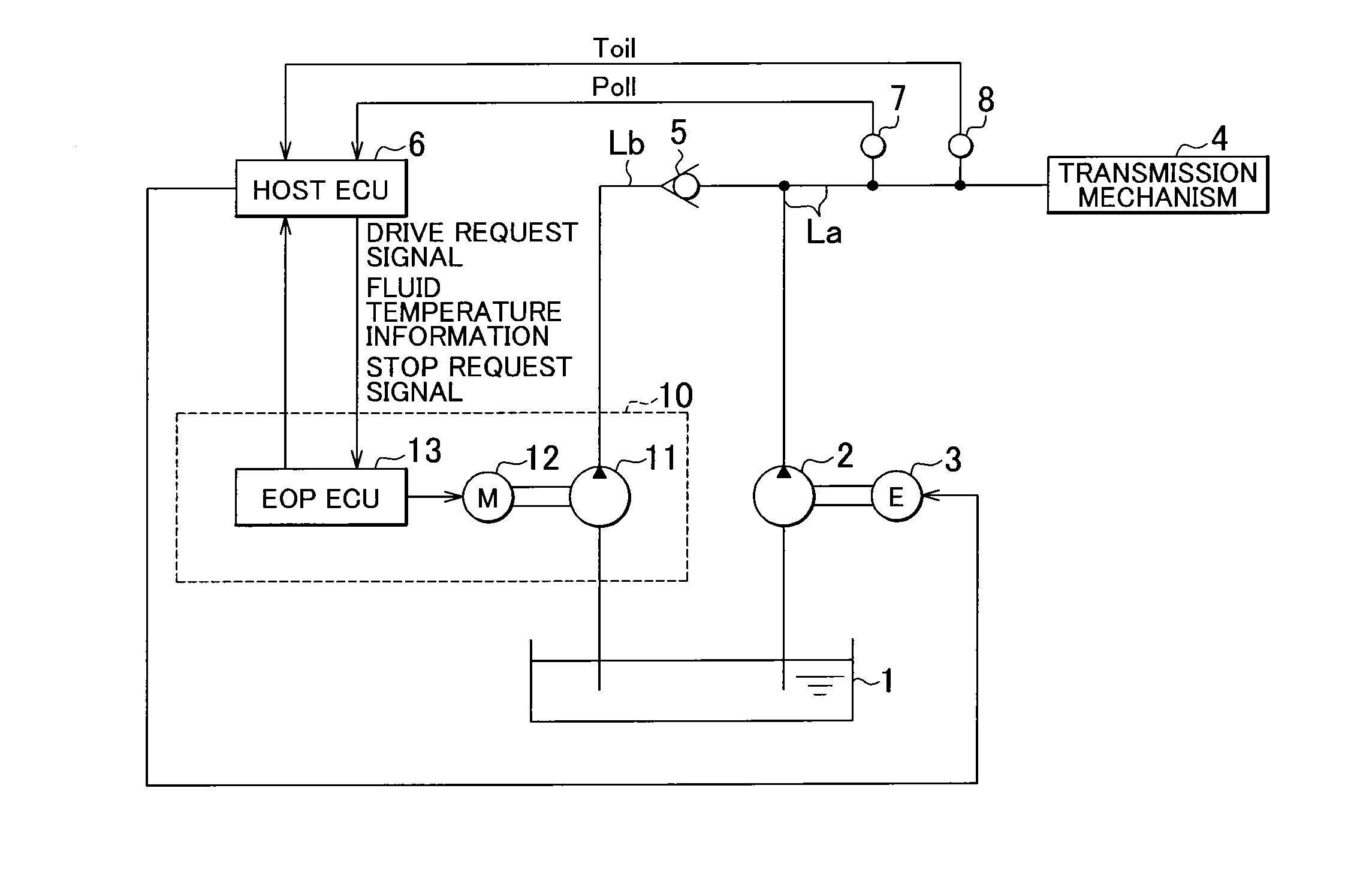
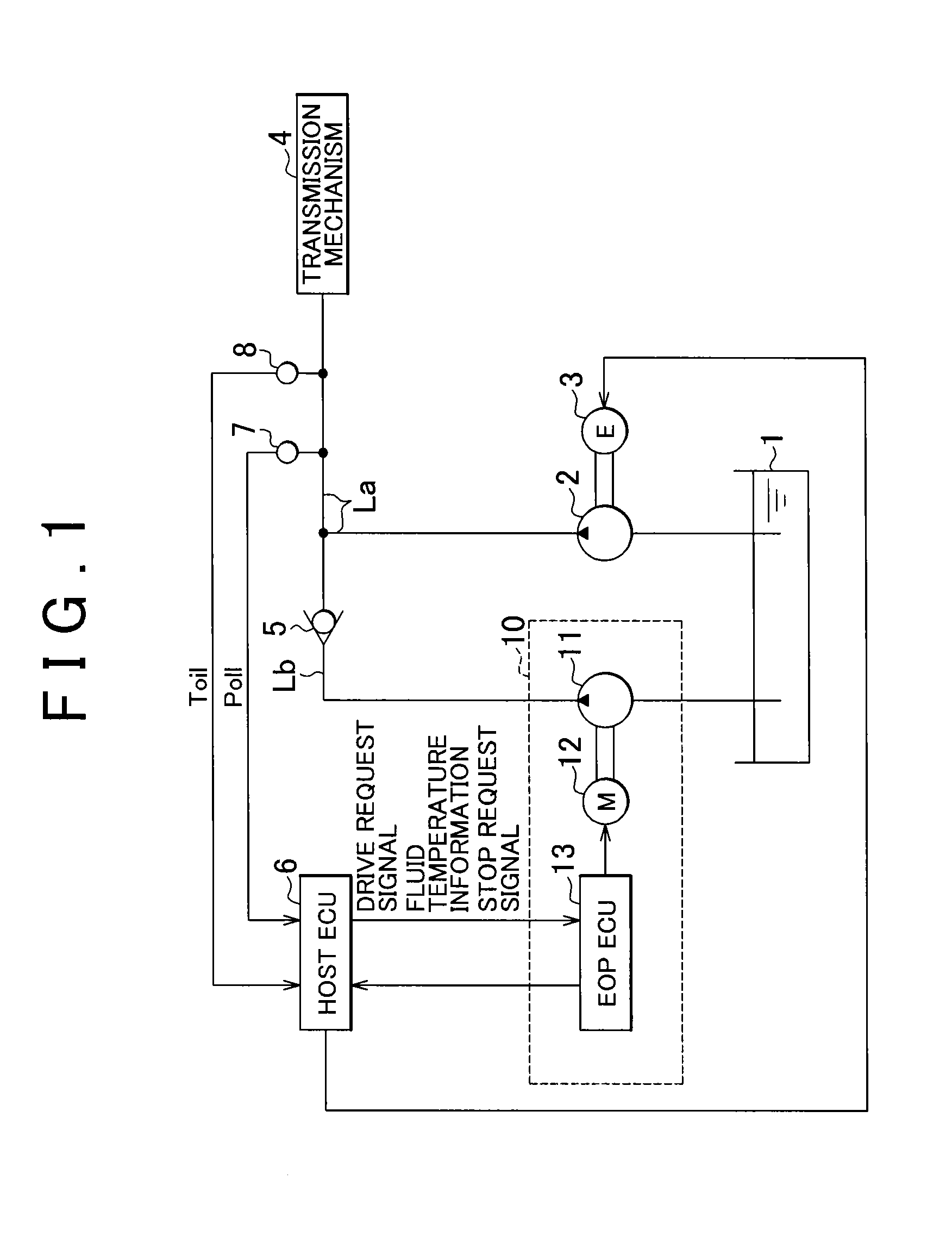
[0052]FIG. 7 shows an electric pump system according to a modified example to the An in-vehicle battery is usually used as a power source for the motor 12. Therefore, when the voltage value of the in-vehicle battery decreases due to aged degradation, or the like, of the in-vehicle battery, the power output from the motor 12 also decreases. Accordingly, the hydraulic pressure of the hydraulic fluid decreases. That is, there is also a correlation between the hydraulic pressure of the hydraulic fluid and the power supply voltage of the motor 12. As shown in FIG. 7 that shows a flowchart corresponding to the estimated hydraulic pressure computing process illustrated in FIG. 4, after the fluid temperature correction gain Kt is set on the basis of the fluid temperature Toil of the hydraulic fluid (step S12), a voltage correction gain Kv may also be set on the basis of the power supply voltage of the motor 12 (step S14). For example, when a reference voltage that is set in advance for the...

third embodiment

In the above-described third embodiment, when the fluid temperature of the hydraulic fluid changes to cross one of the boundaries between the three fluid temperature ranges, the correction gain Ki is changed from the second gain Ki2 to the first gain Ki1. Alternatively, the changed gain may be a value larger than the second gain Ki2 instead of the first gain Ki1.

[0072]In the above-described embodiments, the current command value Ia for the motor 12 is corrected by adding the correction value ΔIa to the current command value Ia or subtracting the correction value ΔIa from the current command value Ia. Alternatively, for example, a multiplication coefficient (gain) may be set for the current command value Ia and the current command value Ia may be corrected by increasing or reducing the gain. That is, the method of correcting the current command value Ia is not particularly limited as long as the current command value Ia for the motor 12 is increased or reduced such that the estimated...


PUM


Abstract

In an electric pump system, hydraulic fluid that is stored in an oil pan is supplied to a transmission mechanism through an oil passage by driving an oil pump with the use of a motor. An EOPECU estimates a hydraulic pressure of the hydraulic fluid on the basis of a driving current for the motor and a rotation speed of the motor, and executes drive control on the motor on the basis of the estimated hydraulic pressure value.

Description

INCORPORATION BY REFERENCE[0001]The disclosure of Japanese Patent Applications No. 2011-288504 filed on Dec. 28, 2011 including the specification, drawings and abstract, is incorporated herein by reference in its entirety.BACKGROUND OF THE INVENTION[0002]1. Field of the Invention[0003]The invention relates generally to an electric pump system, and more specifically to an electric pump system that is suitable for use in a vehicle that has an idling stop function.[0004]2. Description of Related Art[0005]There is a vehicle that has a so-called idling stop function of automatically stopping an engine when the vehicle temporarily stops for parking or temporarily stops at a red light, and automatically starting the engine in response to a driver's vehicle starting operation. In the vehicle that has such an idling stop function, an idling time is reduced and therefore the fuel efficiency is improved.[0006]A mechanical pump that is driven by the engine is usually mounted in the vehicle, and...

Claims


Application Information

Patent Timeline
Patent Type & Authority Applications(United States)
IPC IPC(8): F04B49/06
CPCF16H59/72F04B49/06F16H61/0031F16H61/0021
Inventor UDA, KENGOAOKI, YASUYUKIKAGAWA, HIROKI
Owner JTEKT CORP
Why Eureka
Try Eureka