DC power distribution system

a technology of dc power distribution and power distribution system, which is applied in the direction of emergency power supply arrangement, secondary cell servicing/maintenance, electrochemical generator, etc., can solve the problem of insufficient power for power failur

Inactive Publication Date: 2012-09-13
PANASONIC INTELLECTUAL PROPERTY MANAGEMENT CO LTD
View PDF8 Cites 10 Cited by
  • Summary
  • Abstract
  • Description
  • Claims
  • Application Information

AI Technical Summary

Benefits of technology

[0024]With the present invention, since the storage battery for discharging only in the power failure and the storage battery for discharging at the ordinary times, are separately provided, the backup power required in the power failure can be more reliably ensured.

Problems solved by technology

In this case, it may be impossible to sufficiently ensure the power for the power failure due to the degradation of the storage battery and the like.

Method used


Image

  • DC power distribution system
  • DC power distribution system
  • DC power distribution system

Examples


first embodiment

[0035]A power distribution system of a house in accordance with a first embodiment of the present invention will be described with reference to FIGS. 1 to 3. First, an overview of the system will be given.

[0036]

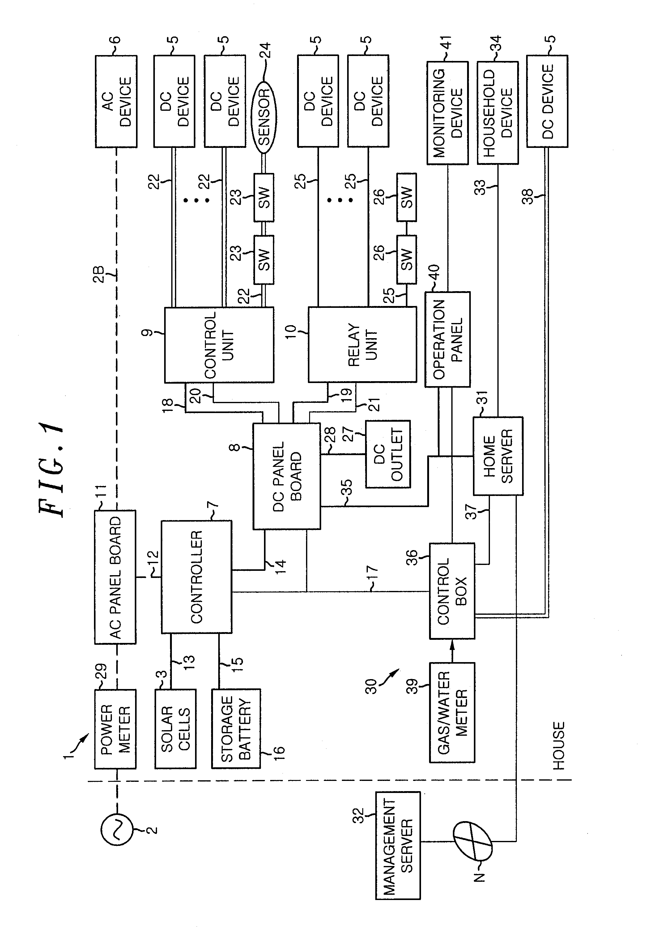
[0037]As shown in FIG. 1, the house is provided with a power supply system 1 to supply power to various devices (illumination device, air conditioner, home appliance, audio and visual device, etc.) installed in the home. The power supply system 1 supplies power to various devices not only from a home commercial power source (AC power source) 2 such that the various devices operate, but also from solar cells 3 producing electricity from sun light. The power supply system 1 supplies power to an AC device 6 being operated by an alternating current power source (AC power source) as well as DC devices 5 being operated by a direct current power source (DC power source).

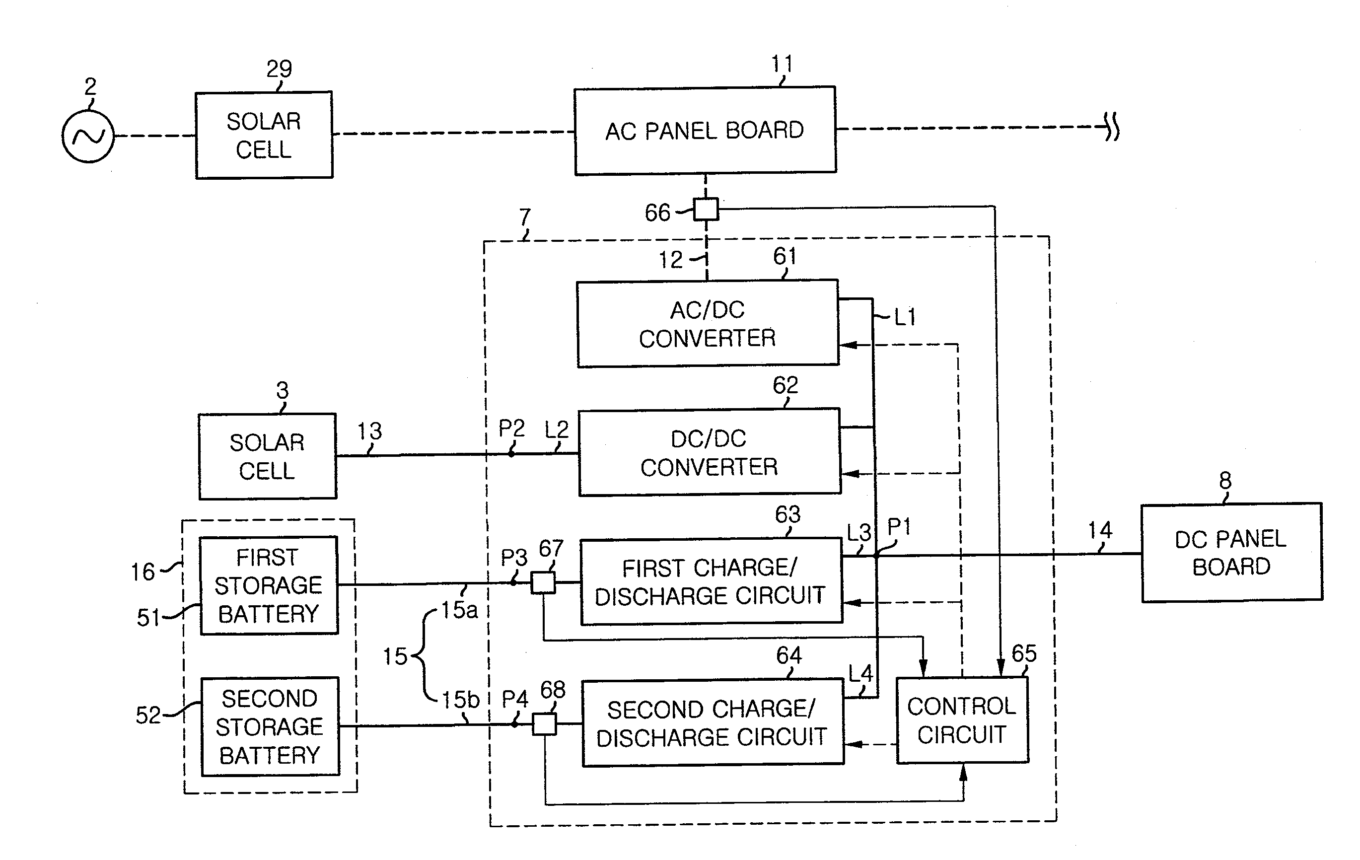
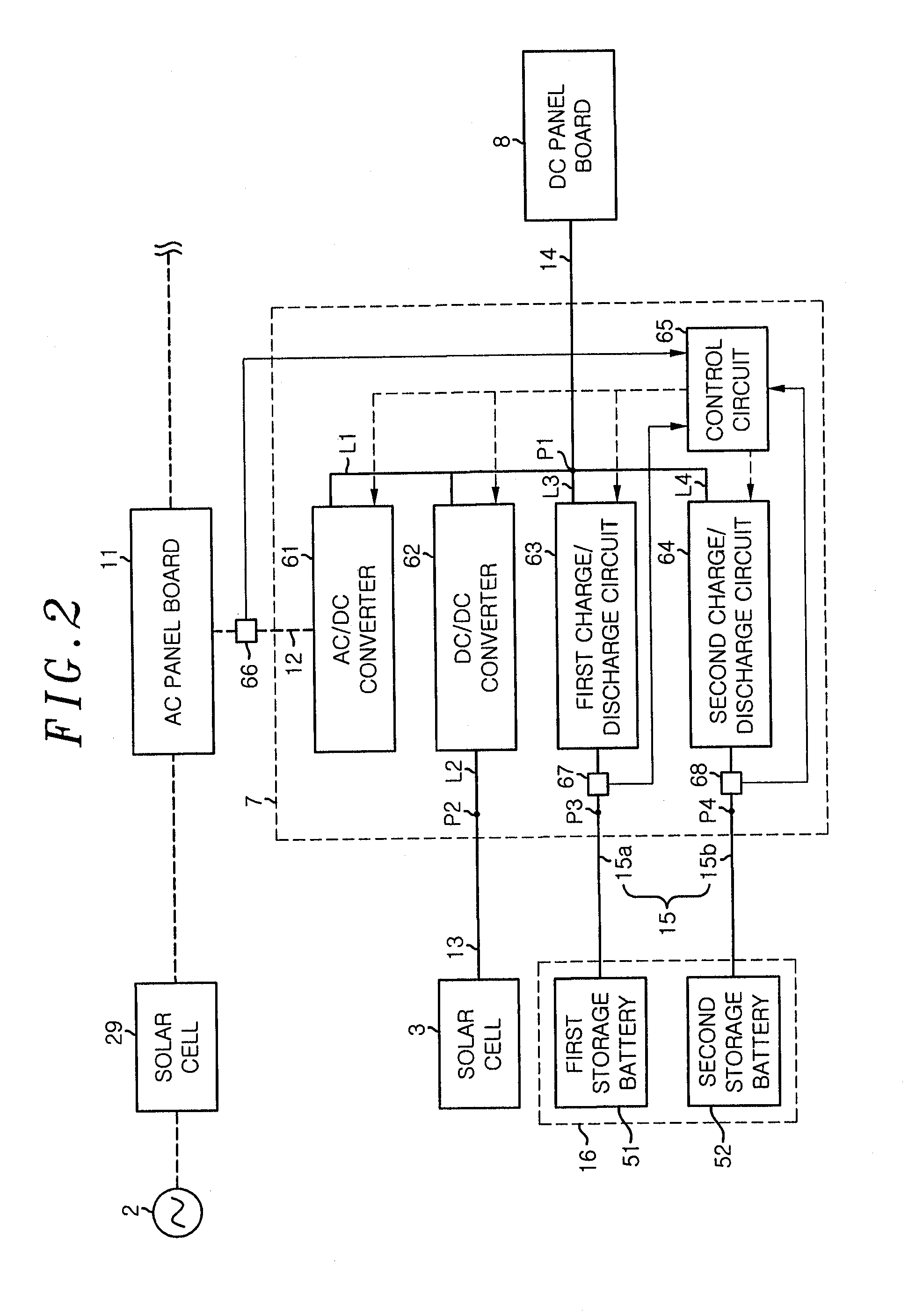
[0038]The power supply system 1 includes a controller 7 and a DC panel board (having a DC breaker therein) 8 as a ...

second embodiment

[0089]Next, a second embodiment of the present invention will be described. The power supply system of this embodiment basically includes the same configuration as shown in FIGS. 1 and 2. Thus, the same components as those of the first embodiment are denoted by the same reference numerals, and a detailed description thereof will be omitted.

[0090]The power supply system 1 of this embodiment is different from the first embodiment in that the roles of the first and second storage batteries 51 and 52 can be switched at a predetermined timing. As shown in graphs of FIGS. 3A and 3B, initially, if the first storage battery 51 is set for the power failure and the second storage battery 52 is set for the normal mode, the first storage battery 51 is maintained in a charged state of a predetermined level (e.g., fully charged state) in the daytime. Further, the second storage battery 52 for the normal mode is charged by the power generated by the solar cell 3 (time t0).

[0091]At night, when it i...

third embodiment

[0102]Next, a third embodiment of the present invention will be described. The power supply system of this embodiment also basically has the same configuration as shown in FIGS. 1 and 2.

[0103]As shown in FIGS. 4A and 4B, the second storage battery 52 is placed under the floor in the house. A configuration under the floor is as follows. That is, as shown in FIG. 4B, a floor 71 of the house includes an opening 72 and a step portion 73 formed at an inner periphery of the opening 72. In the opening 72, a storage box 74 is inserted from the top. The storage box 74 is formed to have an opening at the top, and a brim-shaped flange 75 is formed at a peripheral portion of the opening. The flange 75 is engaged with the step portion 73 of the opening 72 to restrict the downward displacement of the storage box 74. That is, the positioning of the storage box 74 in a vertical direction is made. Further, the storage box 74 is formed of an incombustible material or fire retardant material. In addit...


PUM


Abstract

A DC power distribution system is equipped with a storage device having a first storage battery, which discharges to electrical apparatuses only during power failure, and a second storage battery, which discharges to electrical apparatuses when service is not interrupted. The electricity storage device and electrical apparatuses are supplied with DC power from a power generation device which generates electricity using natural energy, and DC power which has been converted from AC power supplied from a commercial power source. When the power supply from the electricity generation device and the commercial power source is interrupted, the first storage battery discharges power to the electrical apparatuses.

Description

FIELD OF THE INVENTION[0001]The present invention relates to a DC power distribution system.BACKGROUND OF THE INVENTION[0002]Conventionally, there is known a DC power distribution system which distributes a DC power to a DC load by associating an AC / DC converter converting AC power supplied from a power system into DC power with a distributed power source such as a solar cell and fuel cell. Generally, the DC power distribution system includes a storage battery as an emergency power source to supply the DC power to the DC load in an emergency such as a power failure at night. Further, at ordinary times, the storage battery is charged by the DC power supplied from the AC / DC converter or the distributed power source such as a solar cell and fuel cell, and the storage battery is discharged in an emergency to supply the DC power to the DC load.[0003]In the DC distribution system disclosed in Patent Document 1, for example, if a power failure has not occurred in the power system and the r...

Claims


Application Information

Patent Timeline
Patent Type & Authority Applications(United States)
IPC IPC(8): H02J9/06
CPCH01M10/44H01M10/465H02J7/35H02J7/34Y02B10/14Y02B10/72H02J9/061Y02B10/70Y02B10/10Y02E60/10
Inventor KOSHIN, HIROAKIINOUE, TAKESHIKAGAWA, TAKUYAKASAYA, MASATOKIDERA, KAZUNORI
Owner PANASONIC INTELLECTUAL PROPERTY MANAGEMENT CO LTD
Why Eureka
Try Eureka