Terminal block and method of molding it

a terminal block and terminal block technology, applied in the direction of coupling device connection, coating, chemistry apparatus and processes, etc., can solve the problems resin warping and resin peeling, and achieve the effect of reducing the likelihood of voids

Active Publication Date: 2012-09-06
SUMITOMO WIRING SYST LTD
View PDF17 Cites 11 Cited by
  • Summary
  • Abstract
  • Description
  • Claims
  • Application Information

AI Technical Summary

Benefits of technology

[0009]The secondary molding is formed with the adjacent nuts insulated by the insulation wall. Thus, electrical insulation between adjacent nuts is ensured reliably when the primary molding is completed. Further, the secondary molding mold fixes and covers the projection on the upper end of the insulation wall. Thus, the injection pressure of the secondary molding resin cannot incline the insulation wall and the secondary molding is formed evenly around the insulation wall. Accordingly, the secondary molding is less likely to peel off as compared with the case where the secondary molding is formed with an inclined insulation wall. Further, the exposed portion on the upper surface of the secondary molding guarantees that the insulation wall is not inclined in the partition wall. Furthermore, forming the partition in two processes, i.e. by primary molding and secondary processing reduces the likelihood of voids, as compared with the case where the partition is formed only by one molding.
[0010]The exposed portion could be a long straight part. However, resin warping and resin peel-off are likely to occur at an interface between the straight part and the secondary molding portion covering the straight part when heating and cooling are repeated, such as in a heat cycle test. Accordingly, plural exposed portions preferably are arranged in the direction crossing the arrangement direction of the nuts on the upper surface of the secondary molding. As a result, resin warping and resin peel-off can be suppressed at the interface between the exposed portions and the secondary molding.
[0011]An external force on the exposed portion could cause the exposed portion to deform away from the secondary molding and the resin may peel off at the interface between the exposed portion and the secondary molding at the side where the external force acts. Accordingly, a substantially fillet-like incline preferably is formed on the upper surface of the secondary molding and at least partly covers a base end of the exposed portion. The fillet-like incline is likely to follow deformation of the exposed portion when an external force acts on the exposed portion. Thus, the resin is not likely to peel off at the interface between the base end of the exposed portion and the incline.

Problems solved by technology

Furthermore, forming the partition in two processes, i.e. by primary molding and secondary processing reduces the likelihood of voids, as compared with the case where the partition is formed only by one molding.
However, resin warping and resin peel-off are likely to occur at an interface between the straight part and the secondary molding portion covering the straight part when heating and cooling are repeated, such as in a heat cycle test.

Method used


Image

  • Terminal block and method of molding it
  • Terminal block and method of molding it
  • Terminal block and method of molding it

Examples


Embodiment Construction

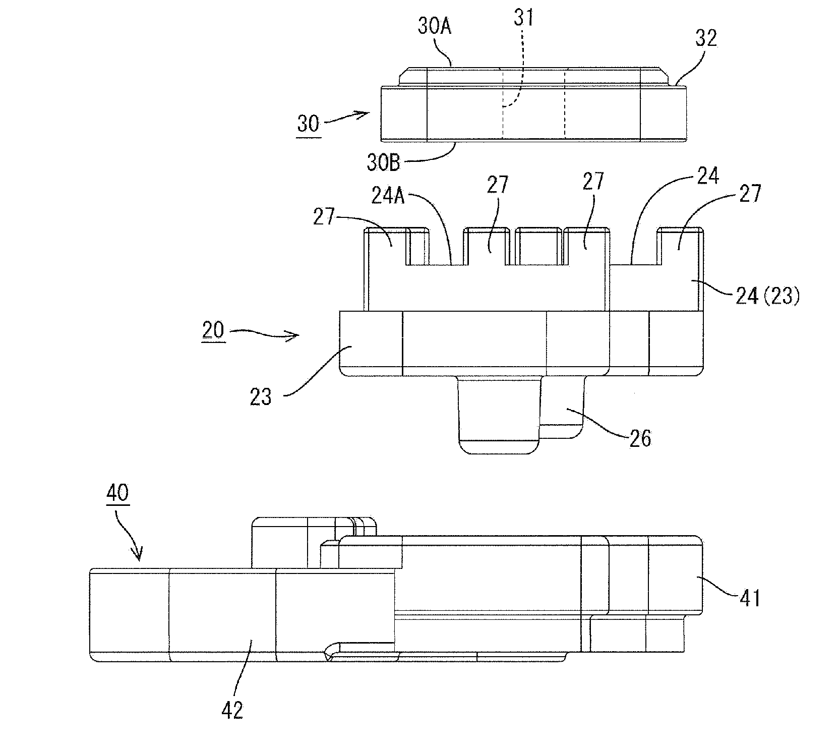
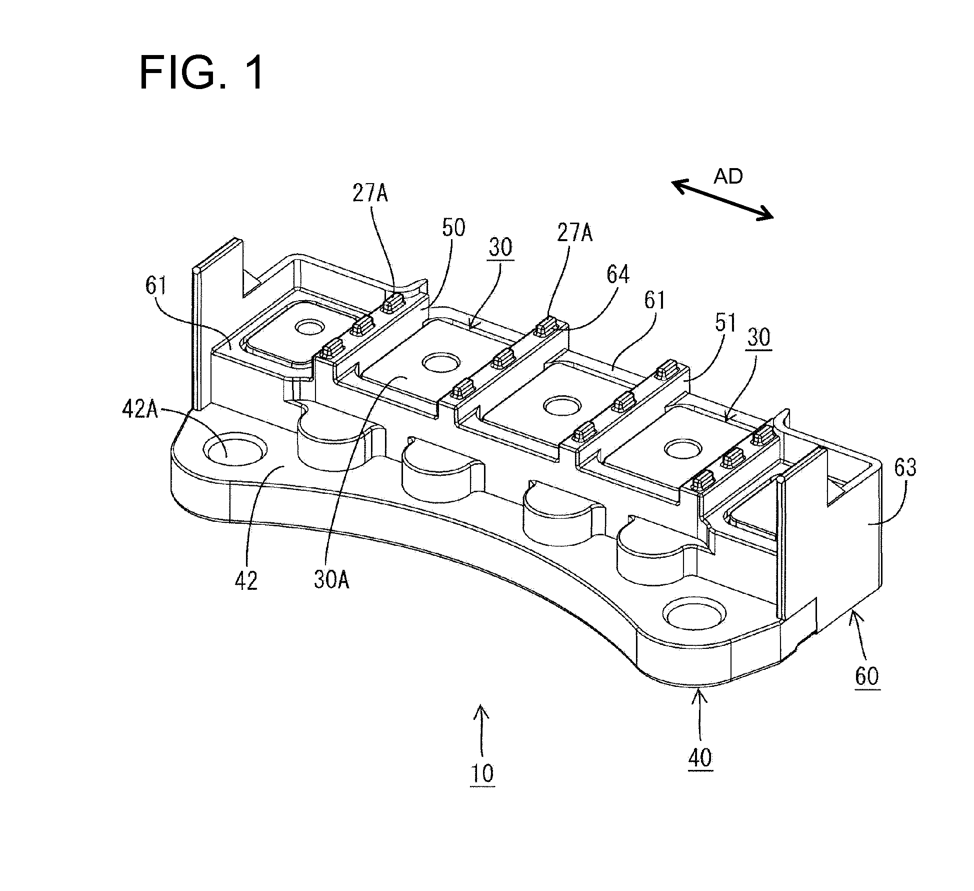
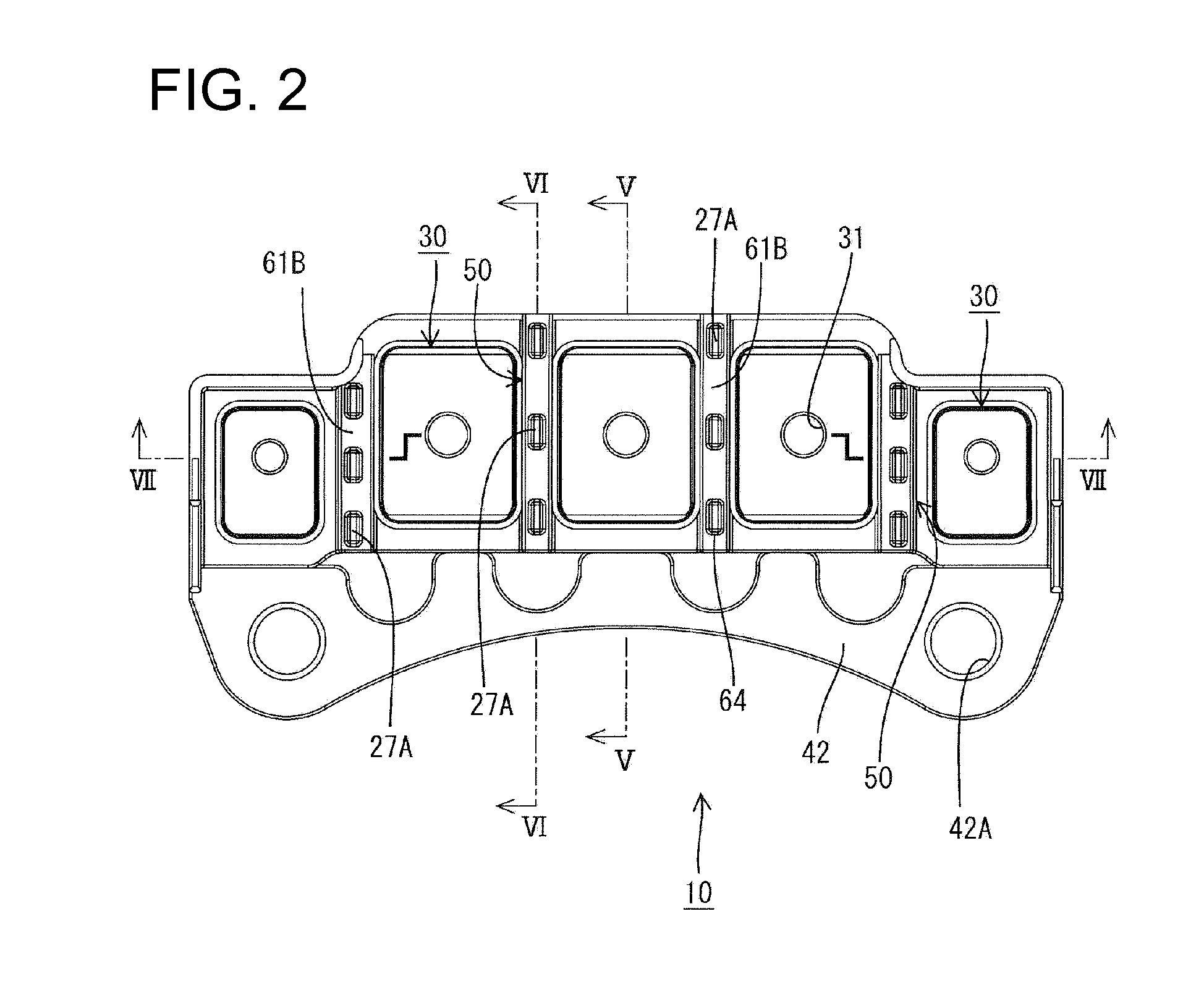
[0034]A terminal block is identified by the number 10 in the figures and is to be mounted on a motor case to be installed in a vehicle, such as an electric vehicle or a hybrid vehicle. The terminal block 10 electrically connects busbars, such as a three-pole busbar in a motor, such as a three-phase alternating current motor, and one or more busbars, such as a three-pole busbar in an inverter.

[0035]The terminal block 10 includes nuts 30 on which the busbars are to be placed. A heat sink 40 is on a side of the nuts 30 opposite the side on which the busbars are to be placed and an insulation plate 20 made e.g. of synthetic resin is sandwiched between the nuts 30 and the heat sink 40. A molded resin portion 60 at least partly covering the insulation plate 20, the nuts 30 and the heat sink 40. Heat from the busbars is transferred to the nuts 30 and then to the heat sink 40 via the insulation plate 20 and is radiated from the heat sink 40 to the motor case. In the following description, a...


PUM

PropertyMeasurementUnit
external forceaaaaaaaaaa
creepage distanceaaaaaaaaaa
electricallyaaaaaaaaaa

Abstract

A terminal block (10) fastens conductors by placing the conductors one above another and fastening bolts and includes a plurality of nuts (30) on which the conductors are to be placed and partition walls (50) partitioning between adjacent nuts (30). Each partition wall (50) includes an insulation wall (24) provided in an insulation plate (20) arranged below the nuts (30) and a molded resin portion (60) covering the upper surface of the insulation wall (24) and the side surface of the insulation wall (24). Exposed portions (27A), which are exposed upper end parts of a projecting portion (27) provided on the insulation wall (24), are provided on the upper end surface of the molded resin portion (60).

Description

BACKGROUND OF THE INVENTION[0001]1. Field of the Invention[0002]The invention relates to a terminal block and to a method of molding a terminal block.[0003]2. Description of the Related Art[0004]Japanese Unexamined Patent Publication No. 2008-98007 discloses a terminal block for electrically connecting conductors, such as busbars, extending from electric devices, such as a motor and an inverter. The terminal block has a body formed by insert molding to include side by side nuts. Conductors in electric devices are placed one over another on the terminal block body and are connected electrically by fastening bolts and the nuts. Synthetic resin partition walls are formed between the nuts and extend up beyond above fastening surfaces of the nuts. The partition walls ensure electrical insulation between the respective nuts and between the conductors placed on the fastening surfaces of the nuts.[0005]Attempts to shape the above-described terminal block by one molding can reduce insulation...

Claims


Application Information

Patent Timeline
Patent Type & Authority Applications(United States)
IPC IPC(8): H01R9/22B29C45/14
CPCH01R4/30H01R9/24H01R13/405B29C70/72B29C45/14065B29C45/14639B29C45/16H01R43/24
Inventor AKUTA, DAISUKE
Owner SUMITOMO WIRING SYST LTD
Why Eureka
Try Eureka