Synchronous torque balance in multiple pump systems

a technology of synchronous torque balance and pump system, which is applied in the direction of adaptive control, positive displacement liquid engine, instruments, etc., can solve the problems of reducing operating efficiency, affecting the overall performance and efficiency of the pump, and affecting the reliability of the system

Active Publication Date: 2012-12-11
ITT MFG ENTERPRISES LLC
View PDF12 Cites 22 Cited by
  • Summary
  • Abstract
  • Description
  • Claims
  • Application Information

AI Technical Summary

Benefits of technology

[0026]According to the present invention, the flow of the multiple pumps is substantially balanced even when pumps have different hydraulic head curves, including the multiple pumps having nearly 1:1 flow balance.

Problems solved by technology

These controllers typically use two methods of control that can negatively affect overall pump performance and efficiency as follows:Fixed Speed Pumps with Variable Speed Trim Pump andMultiple Pump Synchronous Speed.
In order for the trim pump to generate the required pressure at the reduced speed, the variable speed trim pump will be forced back on the pump performance curve which can cause lower operating efficiencies and decreased reliability.
This type of control leads to a flow imbalance between the fixed speed pump and variable speed trim pump.
Both these factors can lead to higher operating cost and decreased pump reliability.
Ultimately, this method leads to a flow dead band in which the only option to operate within this dead band region is to operate the trim pump below the manufactures recommended minimum flow.
This results in Pump 1 operating in the flow dead band region below the recommended minimum flow for the pump.
In conclusion, this form of multi-pump control can lead to flow imbalances between the fixed speed and variable speed trim pump.
This imbalance results in the trim pump being forced back on the pump performance curve which leads to lower pumping efficiencies, decreased pump reliability and uneven wear between the pumps.
However, in practice this may not necessarily result in balanced flow.
However, in practice this situation can be very difficult to maintain as pumps can wear unevenly or a pump with slightly different hydraulics can be added to a pump system at a different time.
It is these factors that can lead to a flow imbalance between the pumps and in a severe case lead to a pump not producing any flow.
In this example running the pumps together at a synchronous speed results in a 2:1 flow imbalance.
Because Pump 2 can not generate the same head as Pump 1 it is forced back on the pump performance curve to compensate which lowers the pump efficiency and decreases pump reliability.
In this situation Pump 2 will not be able to overcome the pressure generated by Pump 1 and will produce no flow causing a dead head situation.
Any deviation from this such as pump wear or using pumps with different hydraulics will result in a flow imbalance and in extreme circumstances a no flow situation.

Method used


Image

  • Synchronous torque balance in multiple pump systems
  • Synchronous torque balance in multiple pump systems
  • Synchronous torque balance in multiple pump systems

Examples


Embodiment Construction

Synchronous Torque Control

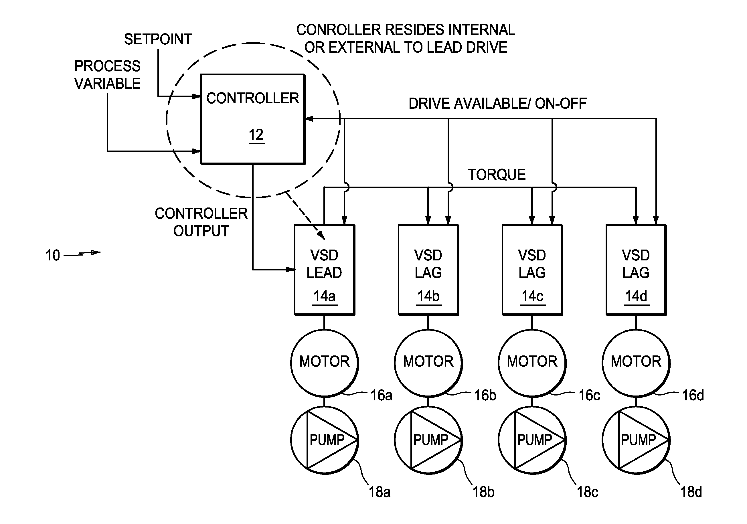
[0038]FIG. 6 is a functional block diagram of a system according to the present invention and generally indicated as 10 having a controller 12 that may take the form of, but not limited to, a VFD, PLC, DCS system, SCADA system that reads a process variable and determines the number of pumps required and at what torque to run the pumps in order to maintain a desired setpoint. The controller 12 is coupled to four variable speed drives (VSDs) 14a, 14b, 14c, 14d; four motors 16a, 16b, 16c, 16d; and four pumps 18a, 18b, 18c, 18d. As shown, the variable speed drive 14a is a lead VSD. The system is described by way of example having four variable speed drives (VSDs), motors and pumps, although the scope of the invention is not intended to be limited to the number of variable speed drives (VSDs), motors and pumps. Embodiments are envisioned, and the scope of the invention is intended to include, systems having a different number of variable speed drives (VSDs), mot...


PUM


Abstract

The present invention provides a new and unique method and apparatus for operating and running multiple pumps in a system together at a substantially synchronous torque to achieve a desired setpoint. Each of the multiple pumps may be operated with a variable speed drive. The present invention may also take the form of the system having the multiple pumps with a system controller for operating and running the multiple pumps, a pump for operating and running in such a system, a system control module for such a system controller, as well as a pump control module for running and operating such a pump.

Description

CROSS-REFERENCE TO RELATED APPLICATIONS[0001]This application claims benefit to provisional patent application Ser. No. 61 / 013,685, filed 14 Dec. 2007, which is hereby incorporated by reference in its entirety.BACKGROUND OF THE INVENTION[0002]1. Field of the Invention[0003]The present invention relates to a method and apparatus for control in a system having multiple pumps.[0004]2. Brief Description of Related Art[0005]There are known devices or controllers that include, but are not limited to, Programmable Logic Controllers (PLC), Distributed Control Systems (DCS), Supervisory Control and Data Acquisition (SCADA) Systems or Variable Speed Drive Macros which coordinate the control of a multiple pump system. These controllers typically use two methods of control that can negatively affect overall pump performance and efficiency as follows:[0006]Fixed Speed Pumps with Variable Speed Trim Pump and[0007]Multiple Pump Synchronous Speed.[0008]Shortcomings of these known devices or control...

Claims


Application Information

Patent Timeline
Patent Type & Authority Patents(United States)
IPC IPC(8): F04B41/06
CPCG05B13/0205F04D13/14F04D15/0066F04D15/0072F04D15/029F04D15/00F04D15/02G05B13/02
Inventor KERNAN, DANIEL J.GANZON, NICOLAS W.
Owner ITT MFG ENTERPRISES LLC
Why Eureka
Try Eureka