Power split transmission

a transmission and power technology, applied in fluid gearings, transmissions, transportation and packaging, etc., can solve the problems of extremely limited structural space for the width and depth of the transmission, and achieve the effect of sufficient rotational speed and higher rotational speed

Active Publication Date: 2012-12-11
ZF FRIEDRICHSHAFEN AG
View PDF107 Cites 31 Cited by
  • Summary
  • Abstract
  • Description
  • Claims
  • Application Information

AI Technical Summary

Benefits of technology

[0012]The clutch for forward drive is preferably positioned coaxially with the drive of the power split transmission, and the clutch for reverse drive is on a shaft separated from the clutch for forward drive. The gear ratios of the gear wheels are preferably designed so that the shaft that is connected to the clutch for reverse drive has a higher rotational speed than the drive shaft that is connected to the clutch for forward drive. This makes it possible to place one or more consumers on the shaft with the clutch for reverse drive, for example a hydraulic pump, which has sufficient rotational speed even with lower rotational speeds on the input drive to the transmission. This hydraulic pump, for example, can be used for the hydraulic supply of the transmission system, as well as for cooling and lubricating. Another hydraulic pump can be used to supply the working hydraulic mechanism.

Problems solved by technology

In addition, the structural space for the width and depth of the transmission is extremely limited in working machines, so that narrow, short transmissions with large axial separations are often used.

Method used


Image

  • Power split transmission
  • Power split transmission
  • Power split transmission

Examples


Embodiment Construction
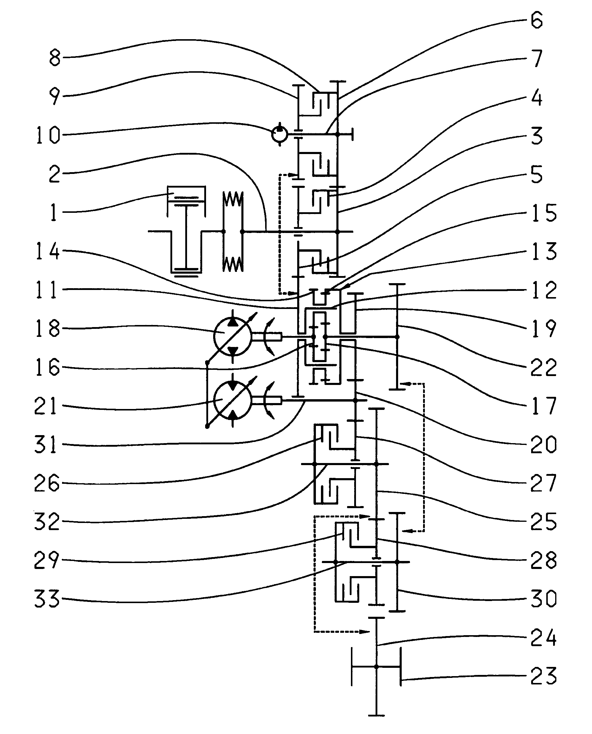
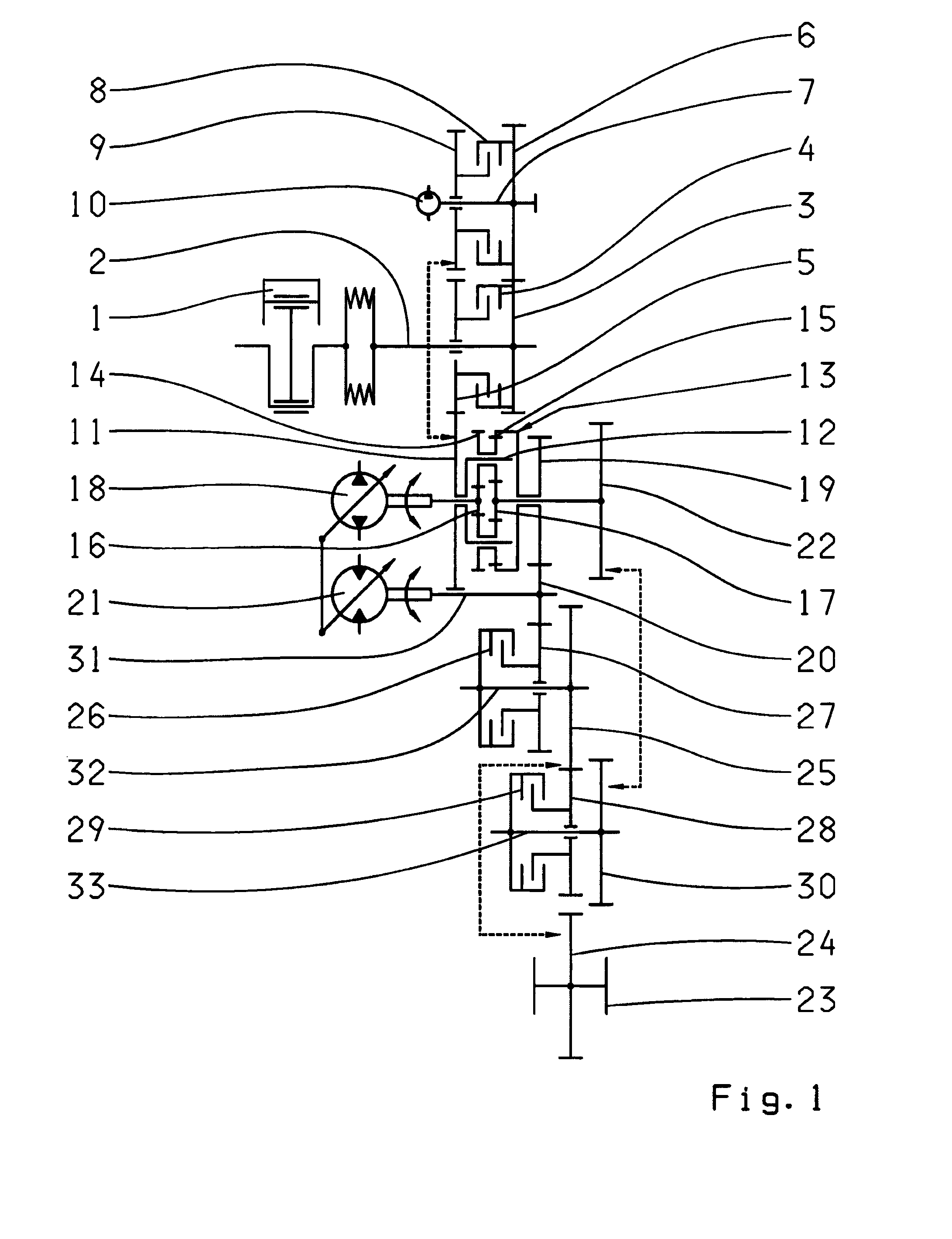
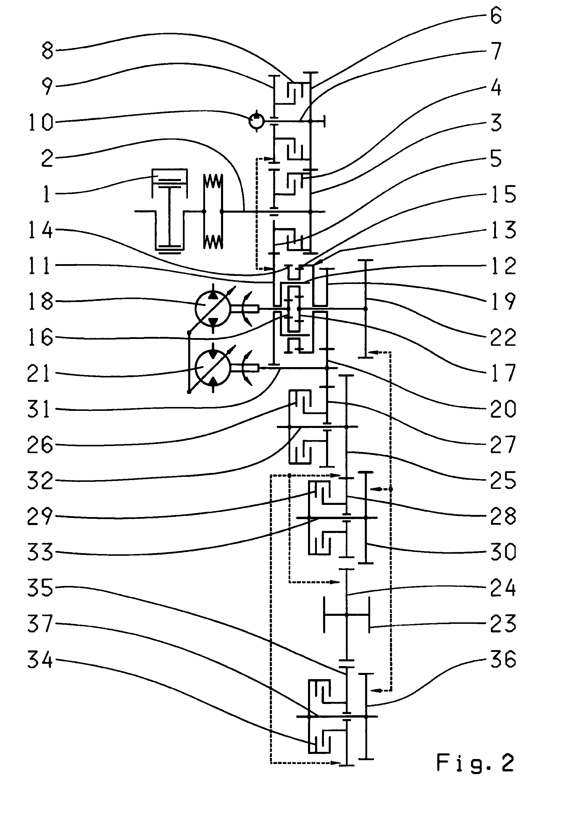
[0020]FIG. 1

[0021]A drive motor 1 drives the input drive shaft 2 for the power split transmission. The drive shaft 2 is connected in a rotationally fixed manner, to a spur gear 3, designed as a fixed gear, and a clutch for forward drive 4. An idler 5 that is connected in a rotationally fixed manner to the clutch for forward drive 4, is located on the input drive shaft 2. The spur gear 3 meshes with a spur gear 6 designed as a fixed gear, which is connected in a rotationally fixed manner, to the shaft 7. The clutch for forward drive 8 is positioned on the shaft 7 and is connected in a rotationally fixed manner to the spur gear 6. The idler 9 is placed on the shaft 7 and is connected in a rotationally fixed manner to the clutch for reverse drive 8. A consumer 10, for example a hydraulic pump, is driven by the shaft 7. The gear ratios are preferably chosen so that the shaft 7, and thus the consumer 10, has a greater rotational speed than the shaft 2. The idler 5 and the idler 9 mesh wi...


PUM


Abstract

A power split transmission for a working machine, such as a wheel loader, having a continuously variable power branch and a mechanical power branch that are summed with one another via a summing gear (13). The summing gear (13) can be connected, via a clutch for forward drive (4) and a clutch for reverse drive (8), to an input drive. The power split transmission has shafts (2, 7; 32, 33) and only a single clutch is located on each shaft.

Description

[0001]This application is a National Stage completion of PCT / EP2008 / 060760 filed Aug. 15, 2008, which claims priority from German patent application serial no. 10 2007 047 194.9 filed Oct. 2, 2007 and German patent application serial no. 10 2008 040 443.8 filed Jul. 16, 2008.FIELD OF THE INVENTION[0002]The invention relates to a power split transmission.BACKGROUND OF THE INVENTION[0003]Such power split transmissions have a continuously variable power branch and a mechanical power branch that are summed by a summing gear set.[0004]The document DE 10 2006 004 223 A1 discloses a power split transmission with a continuously variable power branch and a mechanical power branch that are summed in a summing gear set, wherein the summing gear set consists of a planetary gear set with a double planetary gear, two sun wheels, and an internal geared wheel.[0005]In working machinery, for example such as wheel loaders, the drive motor is positioned above the drive axle so that a transmission is n...

Claims


Application Information

Patent Timeline
Patent Type & Authority Patents(United States)
IPC IPC(8): F16H47/04
CPCF16H47/04F16H3/18F16H2003/0935F16H2037/0873F16H2200/2023F16H2037/107F16H2039/005F16H2200/2005F16H2037/103
Inventor LEGNER, JURGEN
Owner ZF FRIEDRICHSHAFEN AG
Why Eureka
Try Eureka