
Retracting cannula

a cannula and cannula technology, applied in the field of cannula, can solve the problems of limited practical limitations, difficult to perform arthroscopic procedures in small workspaces, and inability to maintain only fluid pressure in small spaces,

Active Publication Date: 2012-12-11
ARTHREX
View PDF11 Cites 68 Cited by
  • Summary
  • Abstract
  • Description
  • Claims
  • Application Information

AI Technical Summary

Benefits of technology

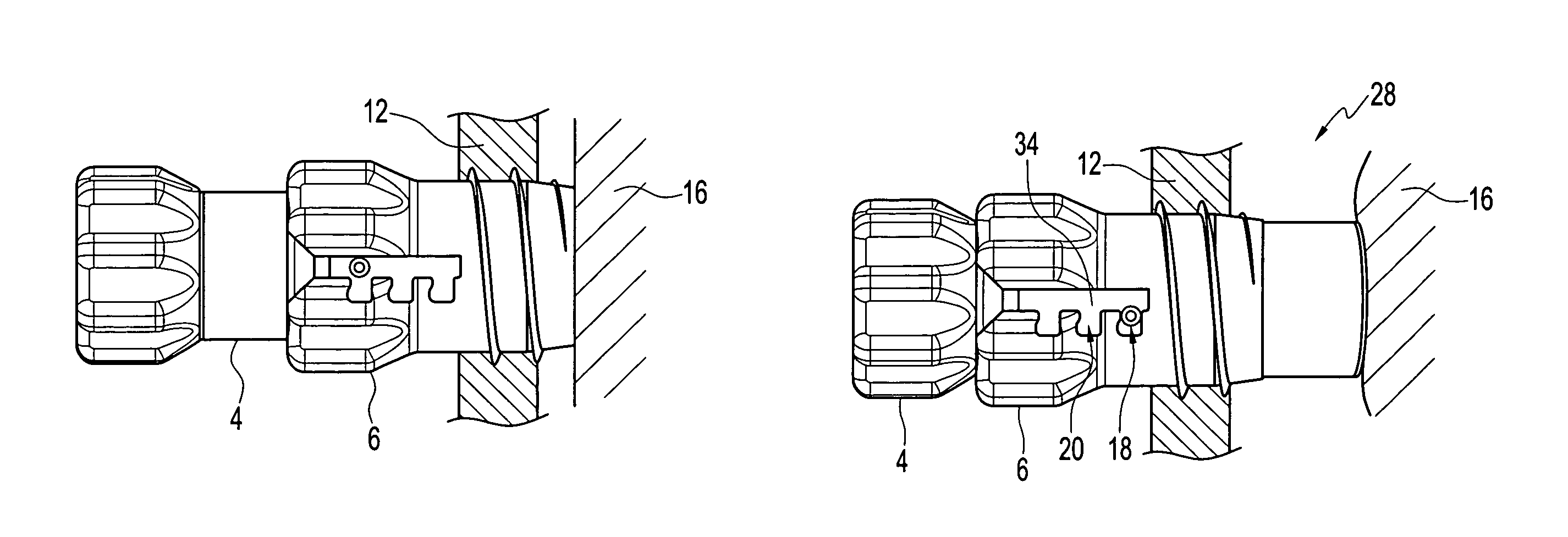
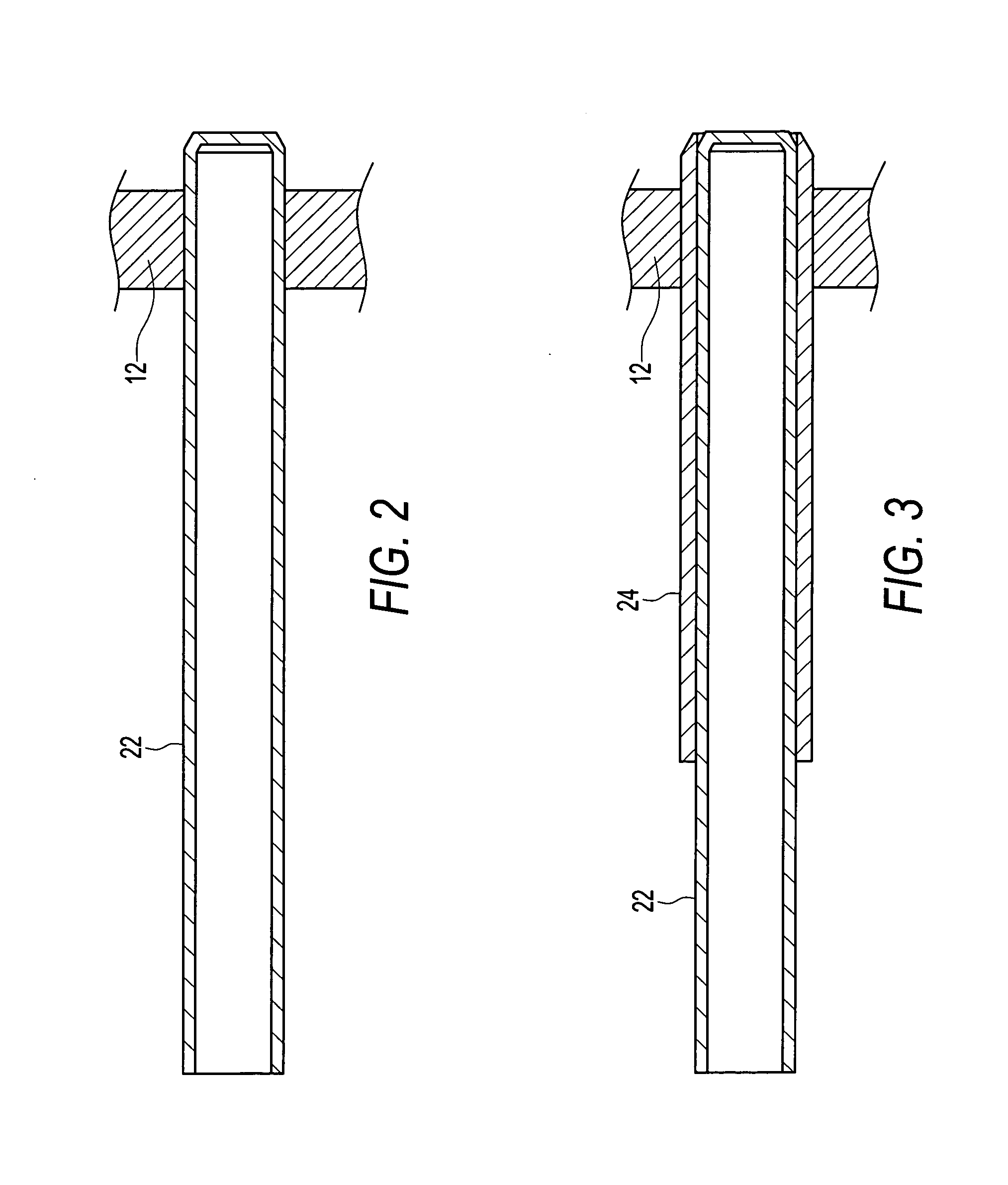
[0005]The retracting cannula of the present invention preferably comprises an outer cannula with a threaded outer surface for engaging the soft tissue to be distracted and an inner cannula with a curved distal end for contacting and sealing the bone surface of a joint, such as the articular surface of a knee. The outer cannula is slidably disposed over the inner cannula. After the inner cannula contacts the articular surface, further relative movement between the inner cannula and the outer cannula causes the soft tissue to distract from the articular surface. The outer cannula can be engaged with the inner cannula to maintain the soft tissue in a distracted position with respect to the articular surface. In a preferred embodiment of the invention, the engagement between the inner and outer cannulas is accomplished with a post on the inner cannula which is rotatably engaged in a J-hook slot in the outer cannula. The retracting cannula is preferably formed of a polymer, preferably a clear polymer such as polycarbonate.
[00

Problems solved by technology

Arthroscopic procedures, however, are difficult to perform in small workspaces, such as within a joint.
The size of the workspace that can be maintained solely by fluid pressure is restricted by practical limitations, however.
The procedure can be performed arthroscopically, but as a practical matter open procedures must be used when articular cores larger than about 10 mm in diameter are indicated, due to the practical limitations of maintaining an arthroscopic workspace of sufficient size to accommodate the larger cores and associated harvesting instruments.

Method used


Image

  • Retracting cannula
  • Retracting cannula
  • Retracting cannula

Examples


Embodiment Construction

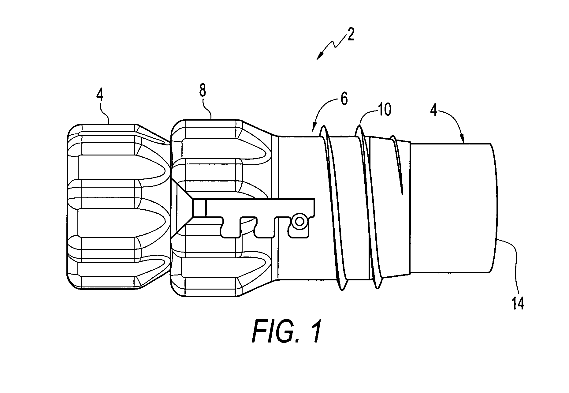
[0014]Referring first to FIG. 1, the retracting cannula of the present invention, identified generally by reference numeral 2, comprises two primary components: an inner cannula 4 and an outer cannula 6. Outer cannula 6 includes a finger grip 8 on its proximal end and has a slightly tapered distal end. Outer cannula 6 is provided with a threaded outer surface 10 for engaging soft tissue 12 to be distracted, as described in greater detail below.

[0015]Inner cannula 4 has a curved distal end 14 for contacting and sealing the surface of tissue 16, such as the surface of a joint, adjacent the soft tissue 12 to be distracted (see FIG. 7). Inner cannula 4 has a smooth outer surface and is dimensioned such that outer cannula 6 can be slidably disposed over inner cannula 4. Inner cannula 4 is also engagable with outer cannula 6 by way of a post 18 on inner cannula 4 which can be rotated and engaged in one of a plurality of J-hook slots 20 provided in outer cannula 6, as described below with ...


PUM


Abstract

A retracting two-piece cannula for distracting soft tissue from bone (e.g., the articular surface of a knee) to provide a surgical workspace for osteochondral repair. After inserting an outer cannula provided with a threaded outer surface into an incision (preferably widened by one or more dilators), the outer cannula is rotated to engage the threaded outer surface with the soft tissue to be distracted. An inner cannula is then inserted into the outer cannula and advanced until it contacts the articular surface. Further relative movement between the inner and outer cannulas causes the outer cannula to be drawn away from the articular surface, thereby retracting the soft tissue and establishing the workspace. The inner and outer cannula are then locked together to maintain the workspace, and an osteochondral core may be introduced through the inner cannula.

Description

[0001]This application claims the benefit of U.S. Provisional Application Ser. No. 60 / 382,343, filed May 23, 2002, the disclosure of which is hereby incorporated by reference.BACKGROUND OF THE INVENTION[0002]Many reconstructive orthopedic surgeries can be performed either as open procedures or as arthroscopic procedures. Rapid recovery from arthroscopic surgical procedures makes them generally more preferred over open surgical procedures. Arthroscopic procedures, however, are difficult to perform in small workspaces, such as within a joint. Typically, an arthroscopic workspace is maintained by the ingress of pressurized fluid into the involved joint to separate the soft tissue from the joint surface. The size of the workspace that can be maintained solely by fluid pressure is restricted by practical limitations, however.[0003]U.S. Pat. No. 5,919,196 issued Jul. 6, 1999 to Bobic et al. discloses a method and apparatus for repair of articular cartilage, such as in the knee, using oste...

Claims


Application Information

Patent Timeline
IPC IPC(8): A61B1/32A61B17/02A61B17/34
CPCA61B17/0281A61B17/3421A61B17/02A61B2017/0268A61B2017/347A61B2017/349
Inventor SCHMIEDING, REINHOLDHACKER, RANDALL L.
Owner ARTHREX
Learn More