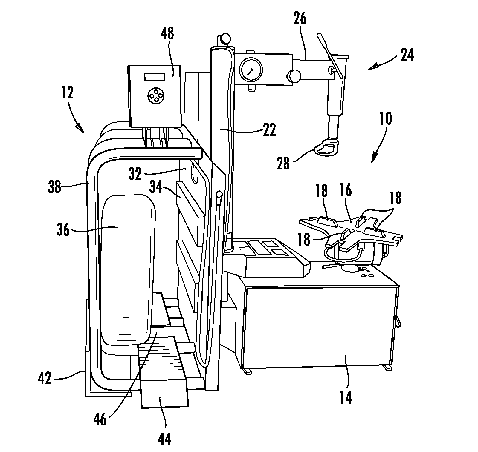
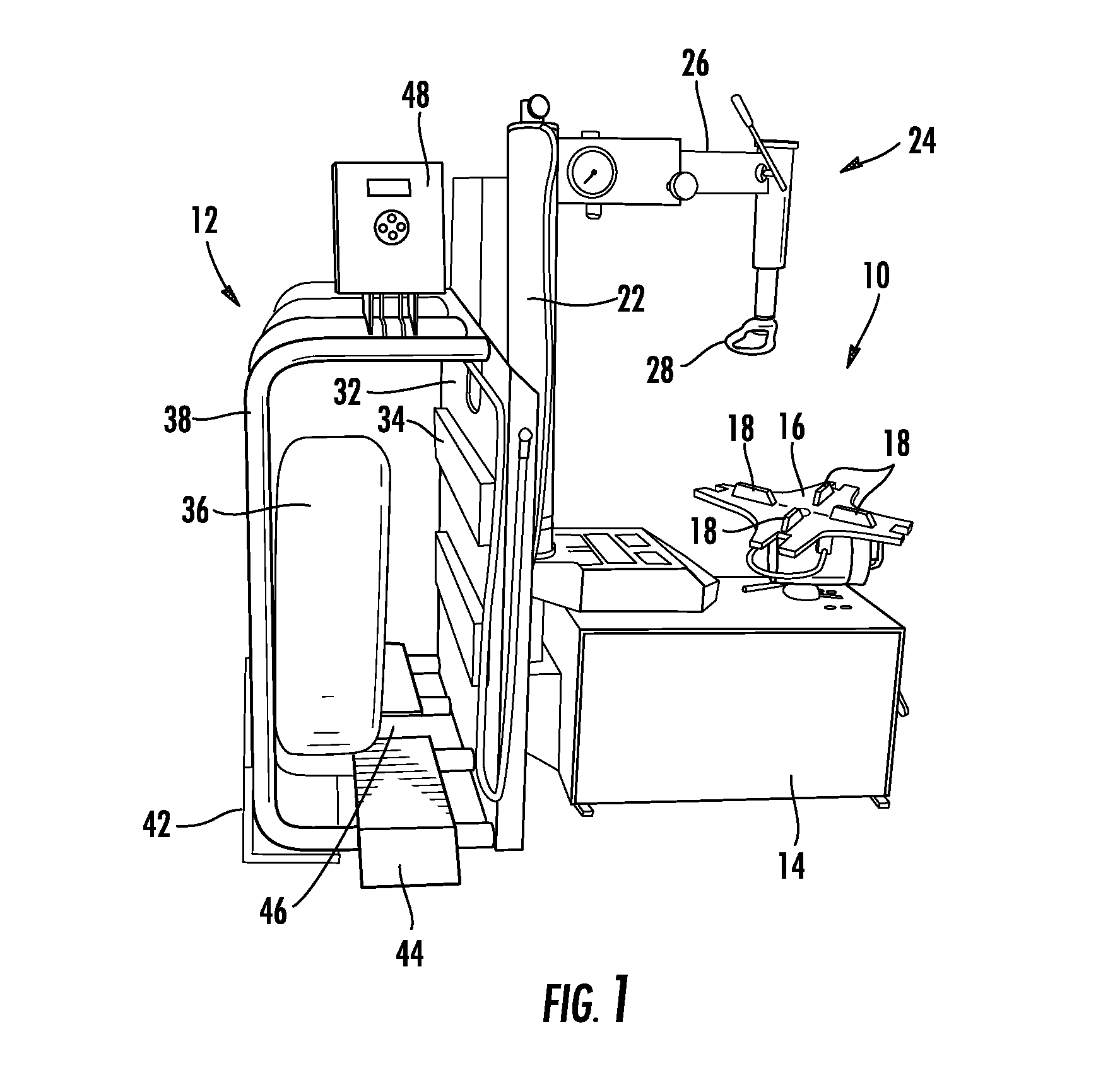
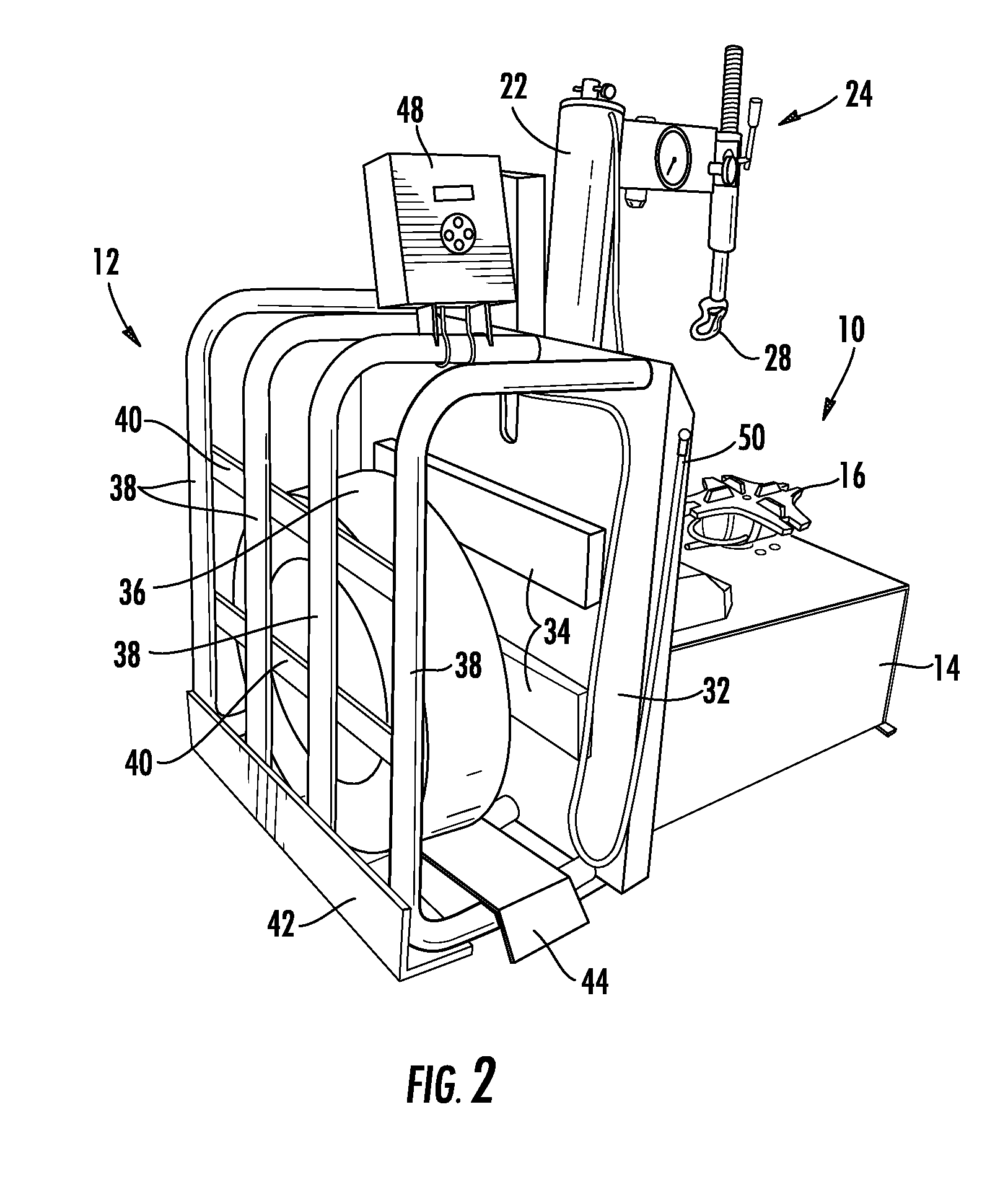
Tire changer with attached inflation cage
a technology of inflation cage and tire changer, which is applied in the field of tire changer, can solve the problems of tire and rim propulsion upward, system failure, and other damage, and achieve the effect of increasing the number of tires and rims, increasing the cost of maintenance and repair, and improving the service li
- Summary
- Abstract
- Description
- Claims
- Application Information
AI Technical Summary
Problems solved by technology
Method used
Image

Examples
Embodiment Construction
[0023]It is to be understood by one of ordinary skill in the art that the present discussion is a description of exemplary embodiments only, and is not intended as limiting the broader aspects of the present invention, which broader aspects are included in the exemplary embodiments.
[0024]The preferred embodiment will be described in relation to a rim holding style tire changer. In this regard, the structure and operation of a rim holding style tire changer device is described in detail in U.S. Pat. No. 6,182,736 to Cunningham et al., incorporated herein by reference in its entirety for all purposes. One skilled in the art will appreciate, however, that aspects of the present invention may be applicable to various other types of tire changers as well.
[0025]Referring now to FIGS. 1-3, a rim holding style tire changer 10 including an attached inflation cage 12 in accordance with the present invention is illustrated. Tire changer 10 includes a base 14 in which a variety of internal mech...
PUM
 Abstract
Description
Claims
Application Information
 - R&D
- Intellectual Property
- Life Sciences
- Materials
- Tech Scout
- Unparalleled Data Quality
- Higher Quality Content
- 60% Fewer Hallucinations
Browse by: Latest US Patents, China's latest patents, Technical Efficacy Thesaurus, Application Domain, Technology Topic, Popular Technical Reports.
© 2025 PatSnap. All rights reserved.Legal|Privacy policy|Modern Slavery Act Transparency Statement|Sitemap|About US| Contact US: help@patsnap.com