Clip

a technology of clip and sleeve, which is applied in the field of clips, can solve the problems of increasing the insertion resistance of the locking leg, the inability to insert, and the inability to obtain deflection rigidity, so as to reduce the width, prevent buckling or damage of the elastic locking member, and increase the insertion resistance.

Active Publication Date: 2012-12-18
PIOLAX CO LTD
View PDF19 Cites 15 Cited by
  • Summary
  • Abstract
  • Description
  • Claims
  • Application Information

AI Technical Summary

Benefits of technology

[0011]It is accordingly an object of the present invention to provide a clip which involves no buckling when the position of a mounting hole is deviated at the time of insertion of the locking leg into the mounting hole, and which allows insertion locking without involving a great increase in insertion resistance, which makes it possible to obtain a substantially uniform deflection rigidity over the entire periphery if a lateral external force is applied to the leg portion in the mounted state.

Problems solved by technology

When the position of the mounting hole is deviated due to dimensional deviation between components, and the leg portion has to be obliquely inserted into the mounting hole, buckling may be caused to make the insertion impossible or breakage may be caused.
Thus, there arises a problem in that the insertion resistance for the locking leg increases.
Thus, it is difficult to obtain a deflection rigidity uniform over the entire periphery, and when a large lateral external force is applied to the leg portion in the mounted state, the engagement members undergo great deformation depending upon the direction and the clip may become subject to detachment.

Method used


Image

  • Clip
  • Clip
  • Clip

Examples


Embodiment Construction

[0045]Next, a clip according to an embodiment of the present invention will be described with reference to FIGS. 1 through 14.

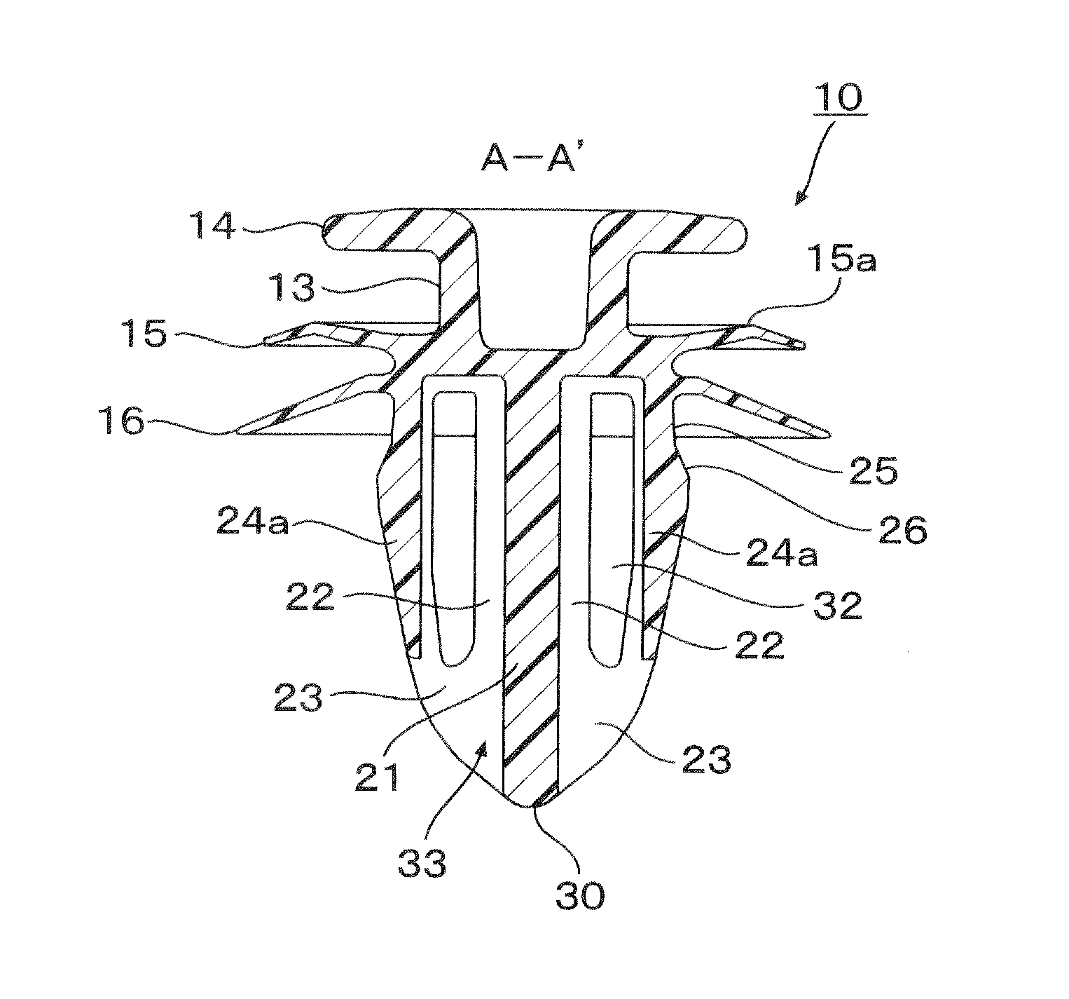
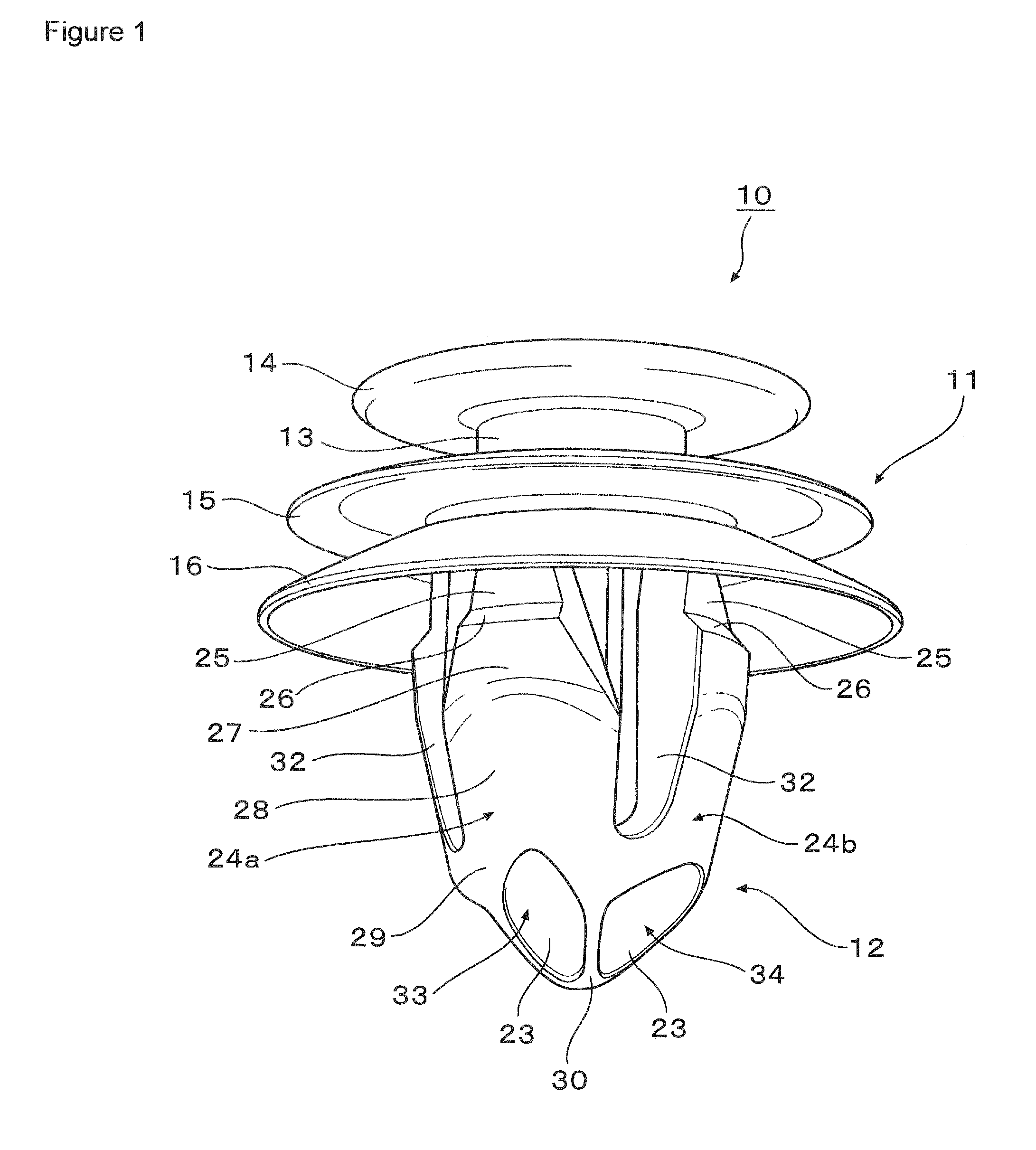
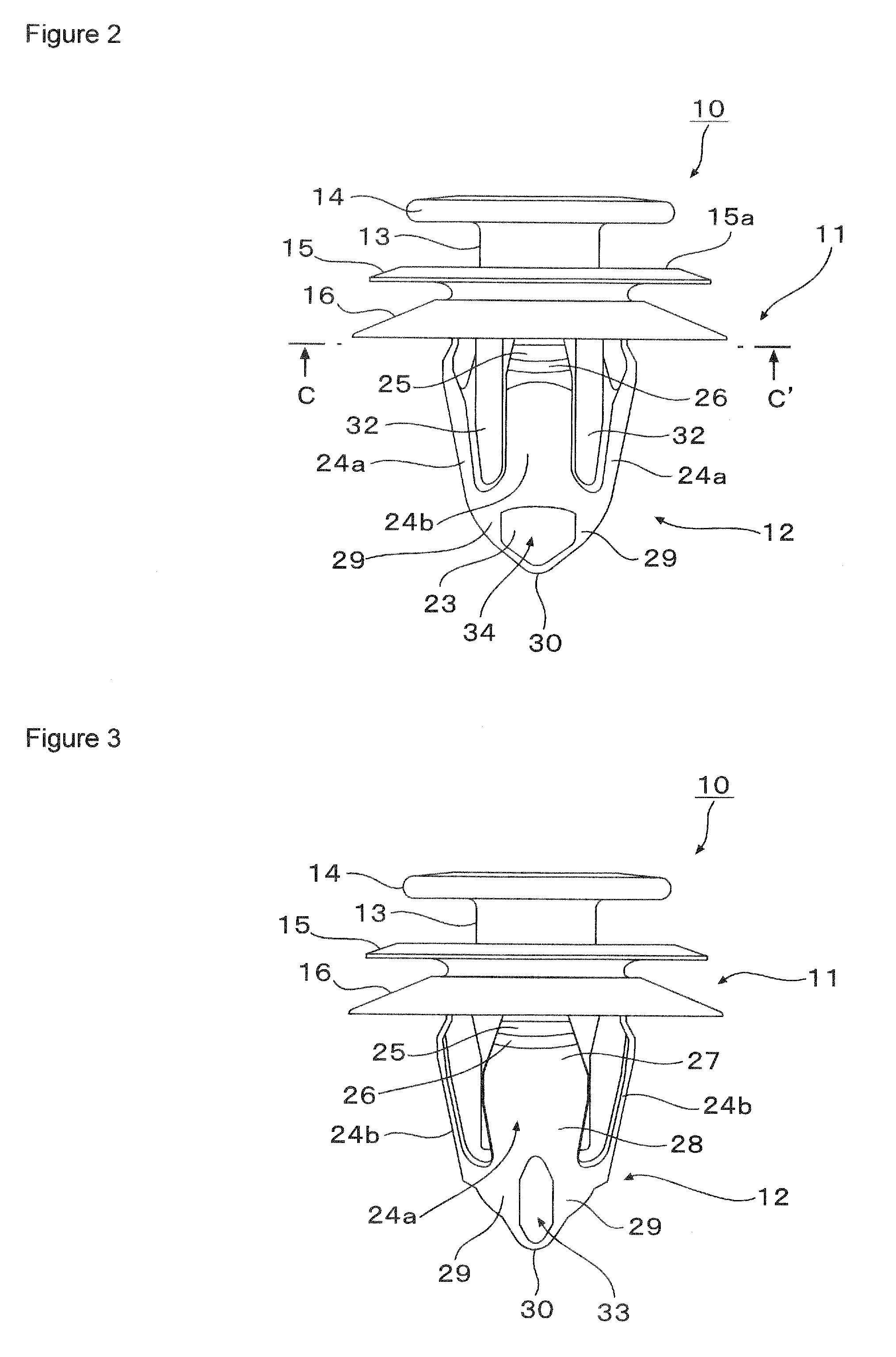
[0046]As shown in FIG. 1, this clip, indicated by reference numeral 10, includes a head portion 11 and a locking leg 12. The head portion 11 has a base portion 13 formed as a bottomed cylinder, a first flange portion 14 formed in the outer periphery of the upper end of the base portion 13, a second flange portion 15 formed in the outer periphery of an intermediate portion of the base portion 13, and a seal flange portion 16 formed in the outer periphery of the lower end portion of the base portion 13. As shown in FIG. 6, the second flange portion 15 has an annular protrusion 15a which is upwardly curved.

[0047]As shown in FIG. 11, the clip 10 is previously fixed to amounting member 17 by being fit-engaged with an engagement groove 18 of the mounting member 17, with the peripheral edge of the engagement groove 18 being held between the first flange portion 14 a...


PUM


Abstract

A clip has a head portion and a locking leg. The locking leg includes a shaft portion vertically extending from the head portion and a plurality of elastic locking legs which are arranged at given intervals at the outer periphery of the shaft portion. Upper ends of the elastic locking legs are connected to the lower surface of the head portion, and each of the elastic locking legs has two portions on two sides, respectively, of a lower end connected to connection ribs extending from the shaft portion. The outer periphery of the shaft portion except for the connection ribs is arranged within an inner side of an inner periphery of the elastic locking members, such that the locking leg can pass through a mounting hole of a panel without the outer periphery of the shaft portion contacting the inner periphery of the elastic locking members.

Description

BACKGROUND OF THE INVENTION[0001]1. Field of the Invention[0002]The present invention relates to a clip used to fix a component, such as an automotive interior component, to a mounting hole of a vehicle body panel or the like.[0003]2. Description of the Related Art[0004]Conventionally, a clip of this type has been used which has a head portion to be fixed to a component and a locking leg extending from the head portion, with the locking leg being inserted into a mounting hole of a vehicle body panel or the like for fixation.[0005]For example, Japanese Utility Model Application Laid-Open No. Hei 4-105615 discloses a clip which is equipped with a head portion and a leg portion. The leg portion is to be inserted into a hole of a panel of a vehicle body or the like to be thereby locked thereto, and includes four legs which independently extend from the head portion. Each leg is integrally molded so as to have an intermediate portion expanding radially outwards and to form a tapered leg ...

Claims


Application Information

Patent Timeline
Patent Type & Authority Patents(United States)
IPC IPC(8): F16B19/00
CPCF16B21/086Y10T24/309
Inventor NAKAZATO, HIROSHI
Owner PIOLAX CO LTD
Why Eureka
Try Eureka