Magnetic tool holder

Active Publication Date: 2012-12-25
DURSTON MFG
View PDF10 Cites 45 Cited by
  • Summary
  • Abstract
  • Description
  • Claims
  • Application Information

AI Technical Summary

Benefits of technology

[0013]Another objective of this invention is the provision of a magnetic tool holder, which is easily mounted.
[001

Problems solved by technology

A single channel with a single magnet interferes with a thin magnetic socket track.
Sometimes, a device for holding sockets in a desired position is rendered ineffective, because

Method used


Image

  • Magnetic tool holder
  • Magnetic tool holder
  • Magnetic tool holder

Examples


Example

[0039]Throughout the figures of the drawings, where the same part appears in more than one figure of the drawings, the same number is applied thereto.

DESCRIPTION OF THE PREFERRED EMBODIMENTS

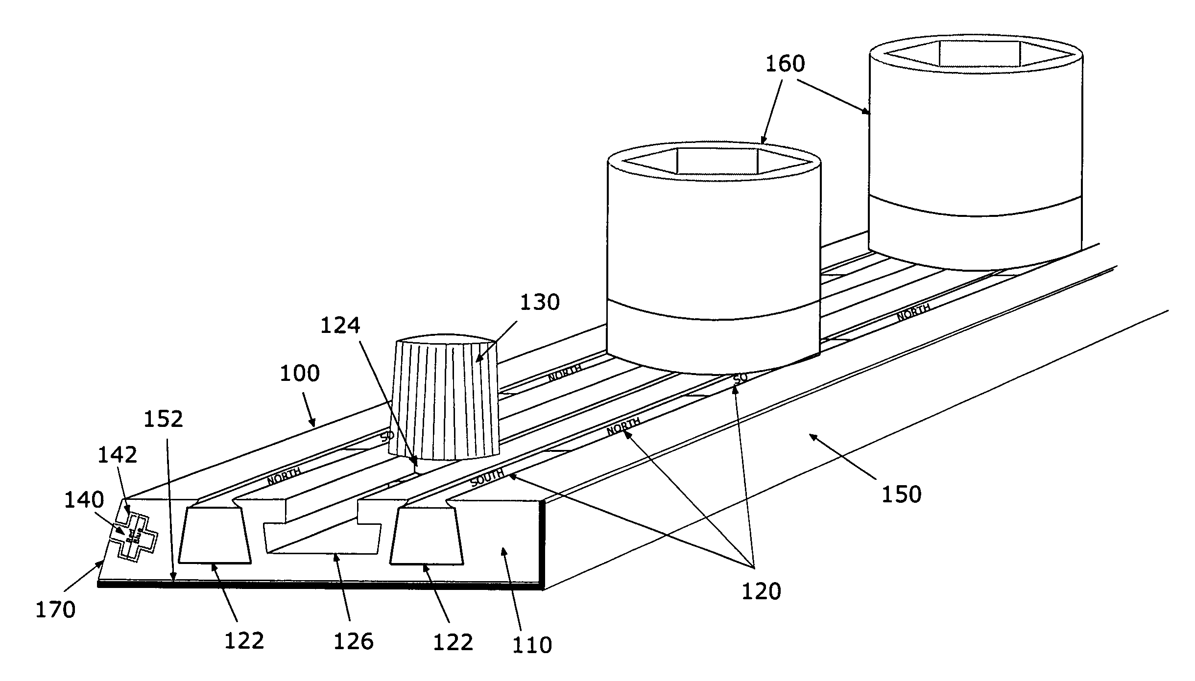
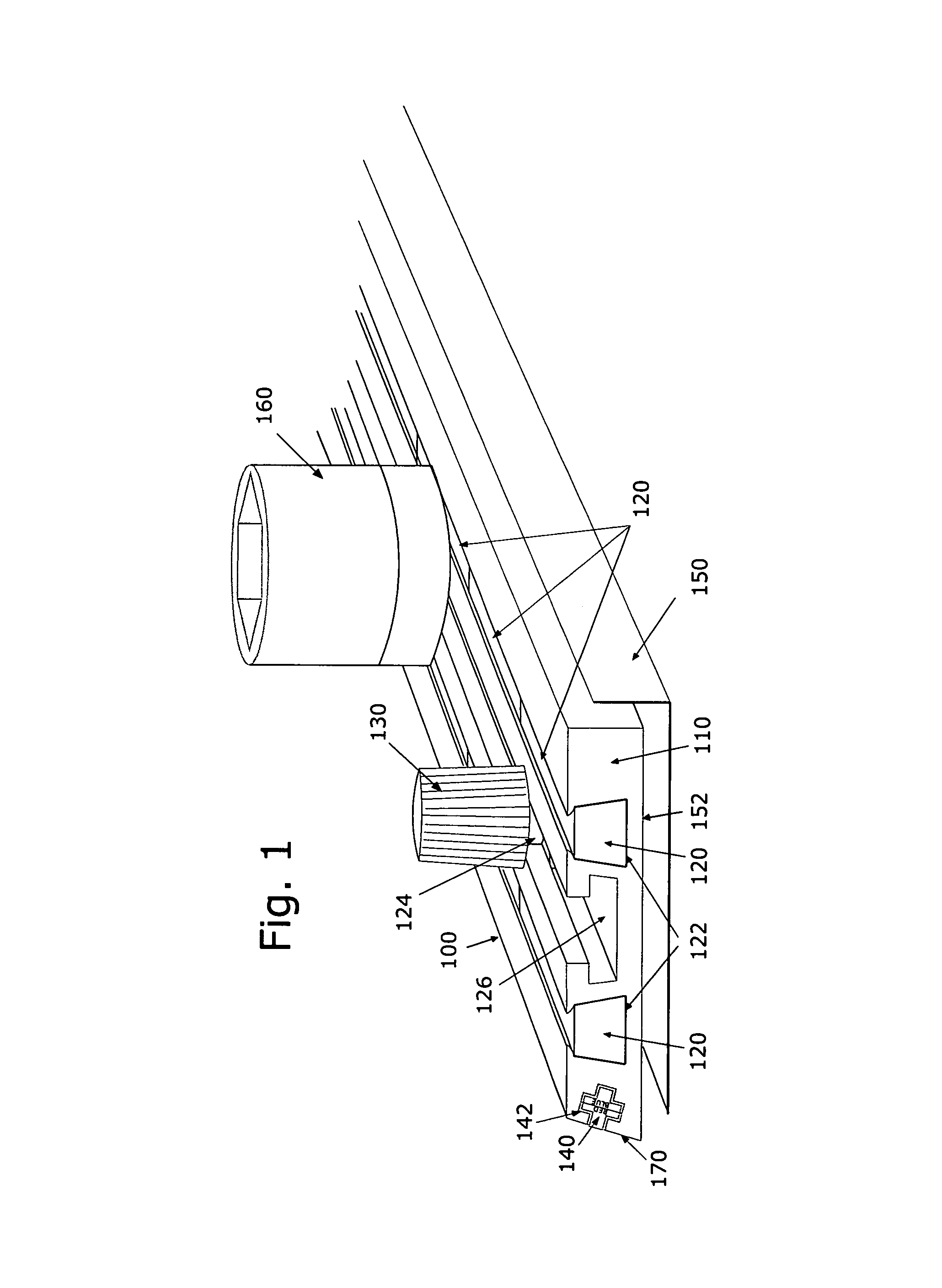
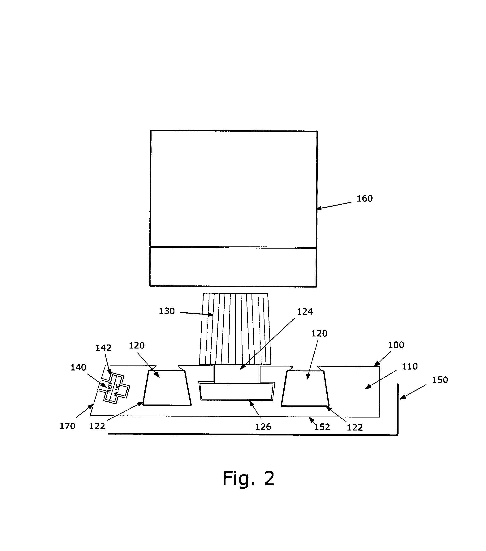
[0040]Reference will now be made in detail to several embodiments of the invention that are illustrated in accompanying drawings. Whenever possible, the same or similar reference numerals are used in the drawings and the description to refer to the same or like parts or steps. The drawings are in simplified form and are not to precise scale. For purposes of convenience and clarity only, directional terms such as top, bottom, left, right, up, over, above, below, beneath, rear, and front, may be used with respect to the drawings. These and similar to directional terms are not to be construed to limit the scope of the invention in any manner. The words attach, connect, couple, and similar terms with their inflectional morphemes do not necessarily denote direct or intermediate connections, but may al...


PUM


Abstract

A tool holder has a housing with magnets mounted therein with a slot therebetween and movable pegs therein cooperating to hold a series of sockets, or a series of screw drivers or bits therefor, or a series of wrenches, or other tools, or combinations thereof, mounted at a desired position on the tool holder.

Description

CROSS REFERENCE TO RELATED APPLICATIONS[0001]This application is a continuation in part of U.S. patent application Ser. No. 12 / 231,581, filed Sep. 4, 2008, now U.S. Pat. No. 7,905,354; filed by the same inventive entity and incorporated herein by reference.[0002]This invention relates to a magnetic tool holder, and more particularly, to a magnetic tool holder which cooperates with a magnetic socket track, in order to support sockets and driver bits on a surface.BACKGROUND OF THE INVENTION[0003]For a mechanic, it is very desirable to have good access to tools. Such access requires the visibility along with ease of removal and replacement. In U.S. Pat. No. 5,501,342 to Ronald J. Geibel; who is the applicant in this application, and which patent is incorporated herein by reference; is disclosed a magnetic strip mounted in a plastic housing for holding sockets in a desired position. Each socket has an appropriate aperture, which receives a fitting on that magnetic socket track.[0004]Thi...

Claims


Application Information

Patent Timeline
IPC IPC(8): B65D85/20
CPCB25H3/003B25H3/06
Inventor GEIBEL, RONALD J.
Owner DURSTON MFG
Why Eureka
Try Eureka