Weightlifting support assembly

a support and weight technology, applied in the field of weightlifting equipment, to achieve the effect of convenient repositioning, convenient guiding, and secure locking

Active Publication Date: 2012-12-25
ROGERS ATHLETIC
View PDF22 Cites 37 Cited by
  • Summary
  • Abstract
  • Description
  • Claims
  • Application Information

AI Technical Summary

Benefits of technology

[0008]The support assembly includes support plates which extend generally perpendicularly from a central support plate to form a generally U-shape. A multitude of studs extend from an inner surface of the support plates to engage the openings and provide a robust support for a significant quantity of weight.
[0009]A pair of generally parallel hook plates extend perpendicularly from the central support plate. The hook plates define an angled intersection to receive a weight bar or the like therein. A non-metallic bumper bridges an edge surface of the hook plates to cushion impacts with the weight bar. A wear pin is mounted at the angled intersection to facilitate positioning of the weight bar thereon.
[0011]In use, the weight support assembly is selectively attached to a desired position along the weight bar frame rack by locating the studs adjacent to openings at a desired height. The weight support assembly is pushed toward the frame member such that that studs engage and are guided by the openings. Concurrent therewith, the lock trigger is driven away from the central support plate by interaction of the latch member with the front face of the frame member such that the bias of a spring is overcome and the latch member is retracted into the lock opening. As the studs slide toward the bottom of the openings, the latch member encounters the lock opening and the latch member engages therewith. The weight support assembly is thereby securely locked into place.
[0012]To remove the weight support assembly, the lock trigger is retracted by locating one or more fingers in the trigger guard aperture and squeezing to overcome the bias of the spring. This is readily achieved by grasping the hook plates. The weight support assembly is then lifted up and out of the openings. As the openings include corners with significant radii, the studs are readily guided thereby. Advantageously, the entire locking and unlocking of the weight support assembly is readily performed with one hand.
[0013]The present invention therefore provides a weight support assembly which will support a significant amount of weight, is securely lockable, yet is readily repositioned along the frame rack.

Problems solved by technology

Although effective, conventional support assemblies typically provide a tradeoff between sturdiness, security when locked along and ease of positioning the frame rack.

Method used


Image

  • Weightlifting support assembly
  • Weightlifting support assembly
  • Weightlifting support assembly

Examples


Embodiment Construction

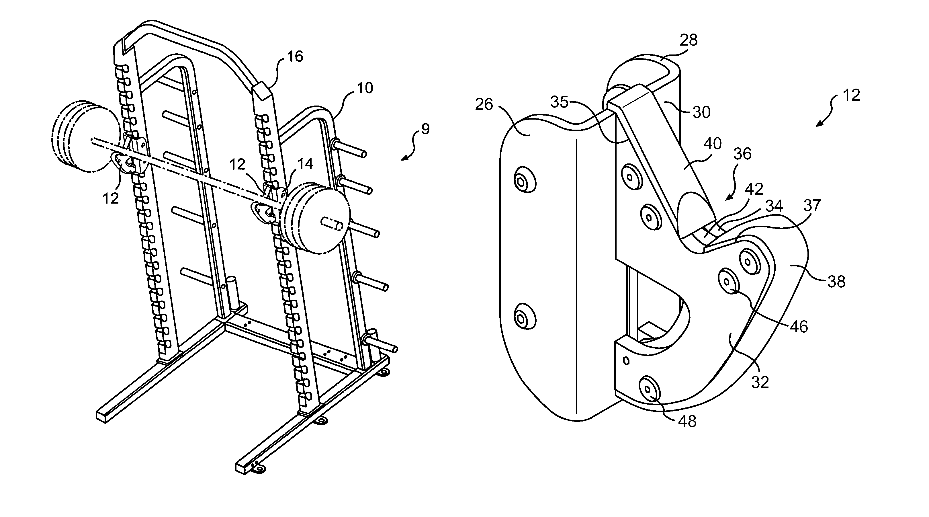
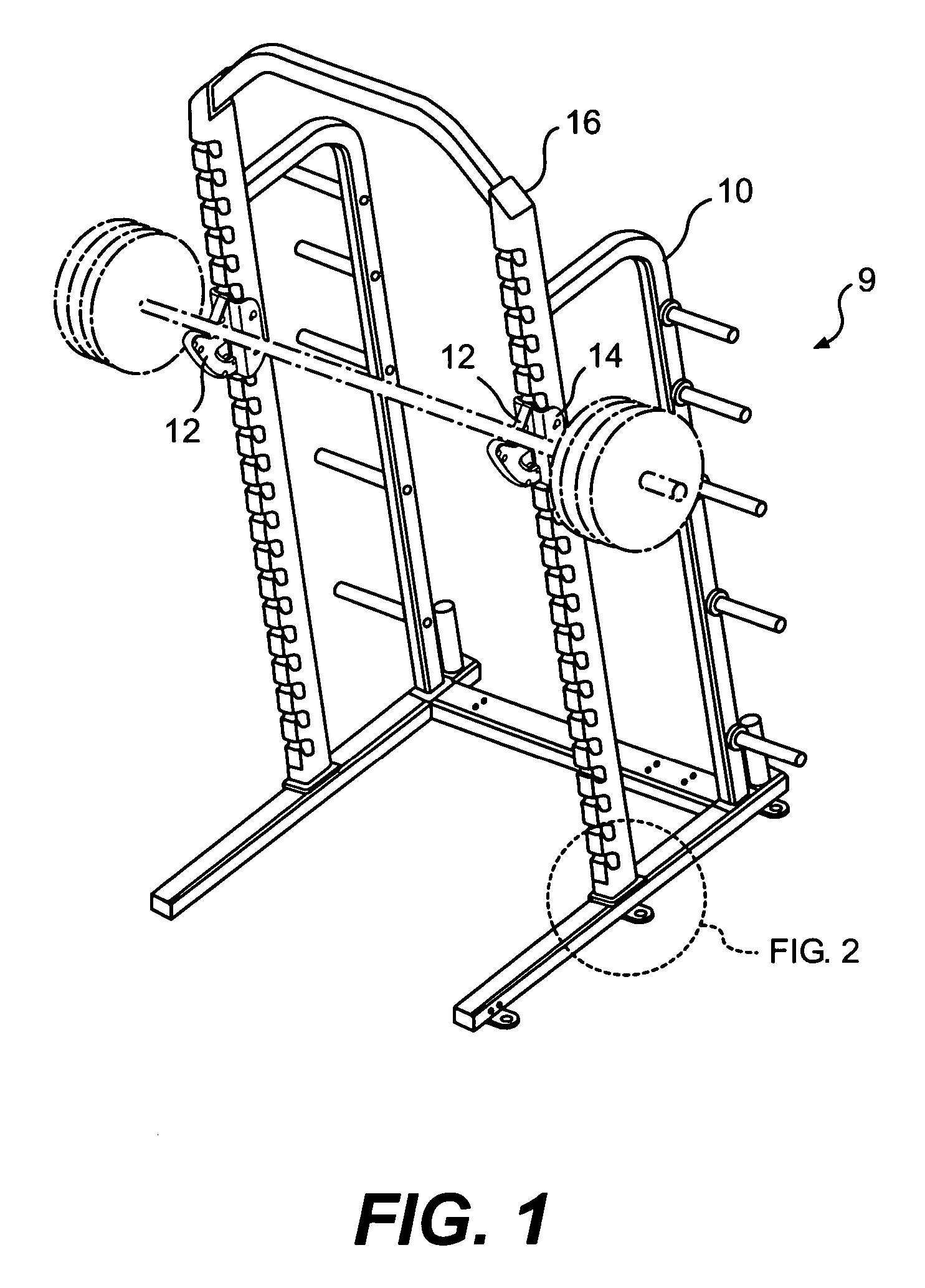
[0023]FIG. 1 illustrates an exploded view of a weightlifting system 9 which includes a weight bar frame rack 10 and weight support assembly 12 (two shown) for attachment thereto. It should be understood that although a particular frame arrangement is illustrated in the disclosed embodiment, other arrangements will be usable with the present invention.

[0024]The frame rack 10 includes a multitude of openings 14 along an upright frame member 16 which receive the weight support assembly 12 such that the support assembly 12 may be located at various positions along the frame rack 10. Each opening 14 is separated from the next by approximately four inches to provide significant incremental adjustment, however, any separation will be usable with the present invention.

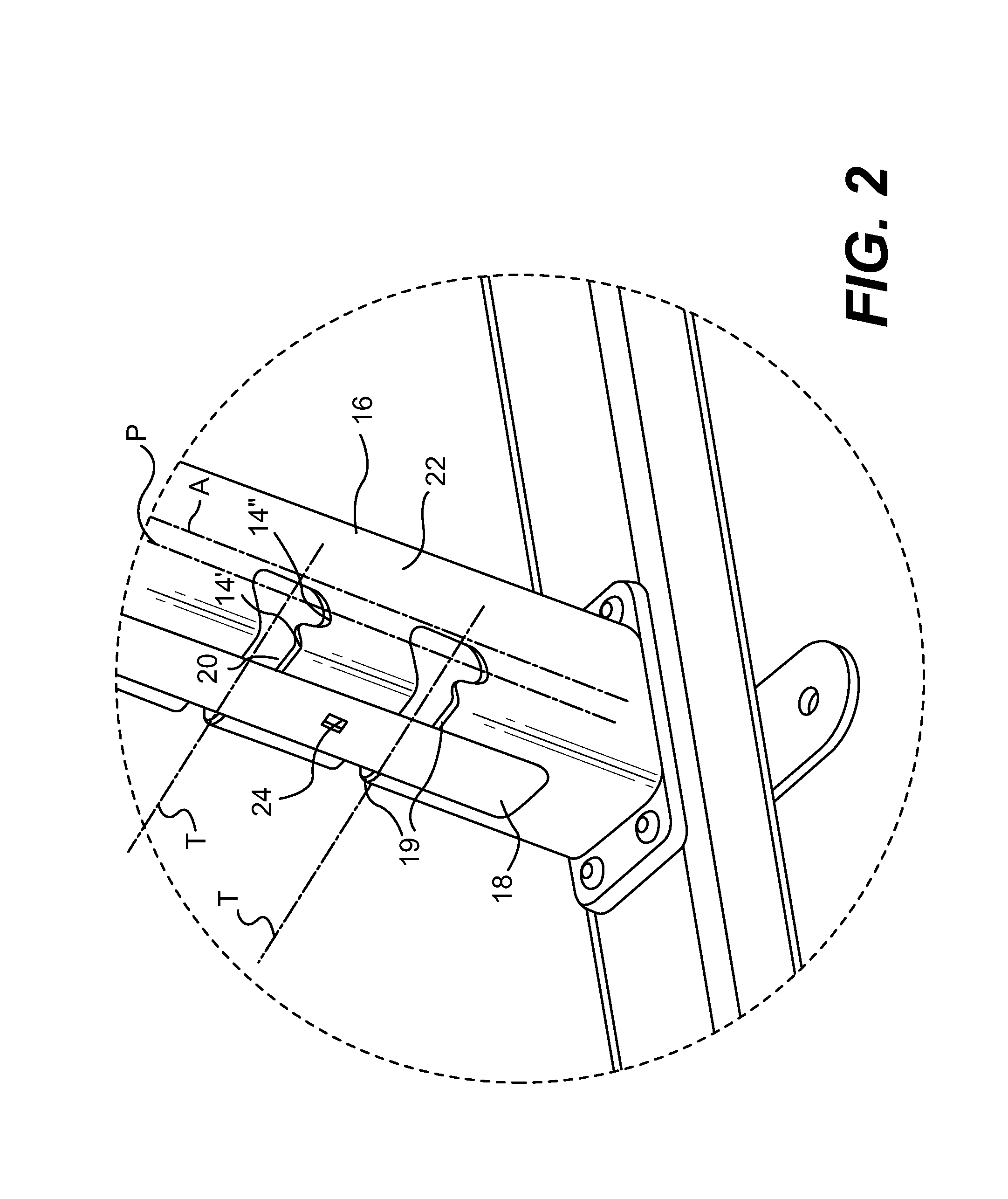
[0025]Referring to FIG. 2, each upright frame member 16 defines a longitudinal axis A which extends vertically relative to the ground. The upright frame member 16 is generally rectilinear in shape and is preferably manufacture...


PUM


Abstract

A weightlifting system includes a weight bar frame rack which includes a multitude of openings along an upright to receive a weight support assembly at various positions along the frame rack. The support assembly includes a multitude of studs which extend from an inner surface of a U-shaped support plate to engage the openings and provide a robust weight support which will bear a significant quantity of weight. In use, the weight support assembly is pushed into and down the upright such that that the studs engage and are guided by the openings. Concurrent therewith, a spring bias is overcome until a latch member encounters a lock opening to securely lock the support into the desired position. To remove the weight support assembly a lock trigger is retracted and the weight support assembly is lifted up and out of the openings. The entire locking and unlocking of the weight support assembly is readily performed with one hand.

Description

BACKGROUND OF THE INVENTION[0001]The present invention relates to weightlifting equipment, and more particularly to a support hook assembly for resting a weight bar.[0002]Weightlifters perform various exercises for the purpose of developing particular muscles throughout the body. These exercises can be performed through the use of free weights, such as barbells, or with machines. Many weightlifters prefer free weights because free weights permit the lifter to perform the exercises in a natural motion while utilizing pure body leverage in performing the exercise. This facilitates isolation of particular muscle groups and simulates actual athletic sports motions. The support assembly also often operates to spot the lifter and prevent the free weight from being dropped past a particular point.[0003]Between “sets” free weights are rested upon a support assembly which mounts to a weight bar frame rack. The support assembly is also adjustable relative to the frame rack to locate the weigh...

Claims


Application Information

Patent Timeline
Patent Type & Authority Patents(United States)
IPC IPC(8): A63B21/078A63B21/06
CPCA63B21/078A63B71/0036
Inventor ROGERS, ORLEY DAVIDHOCKEMEYER, TIMOTHY JOHN
Owner ROGERS ATHLETIC
Why Eureka
Try Eureka