Defining an optimal topology for a group of logical switches

a technology of logical switches and topologies, applied in the field of network fabric virtualization, can solve problems such as the scalability of large layer 2 (l2) fabrics

Active Publication Date: 2012-12-25
AVAGO TECH INT SALES PTE LTD
View PDF19 Cites 381 Cited by
  • Summary
  • Abstract
  • Description
  • Claims
  • Application Information

AI Technical Summary

Benefits of technology

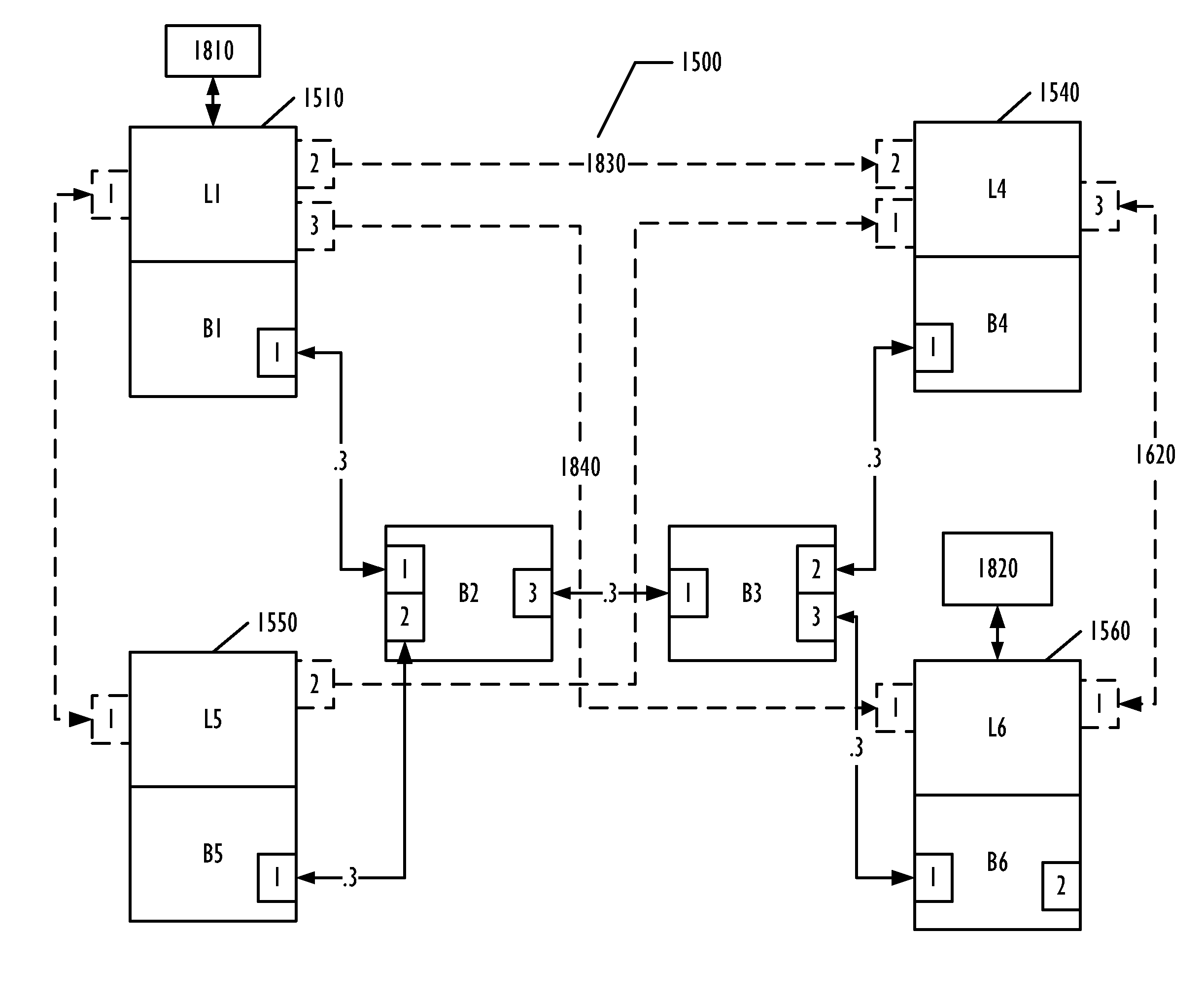
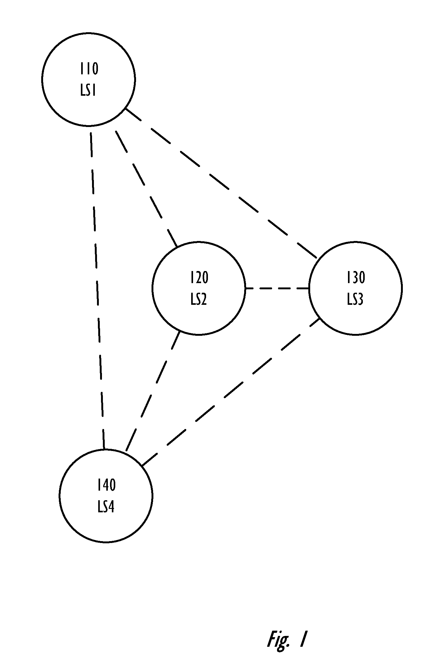
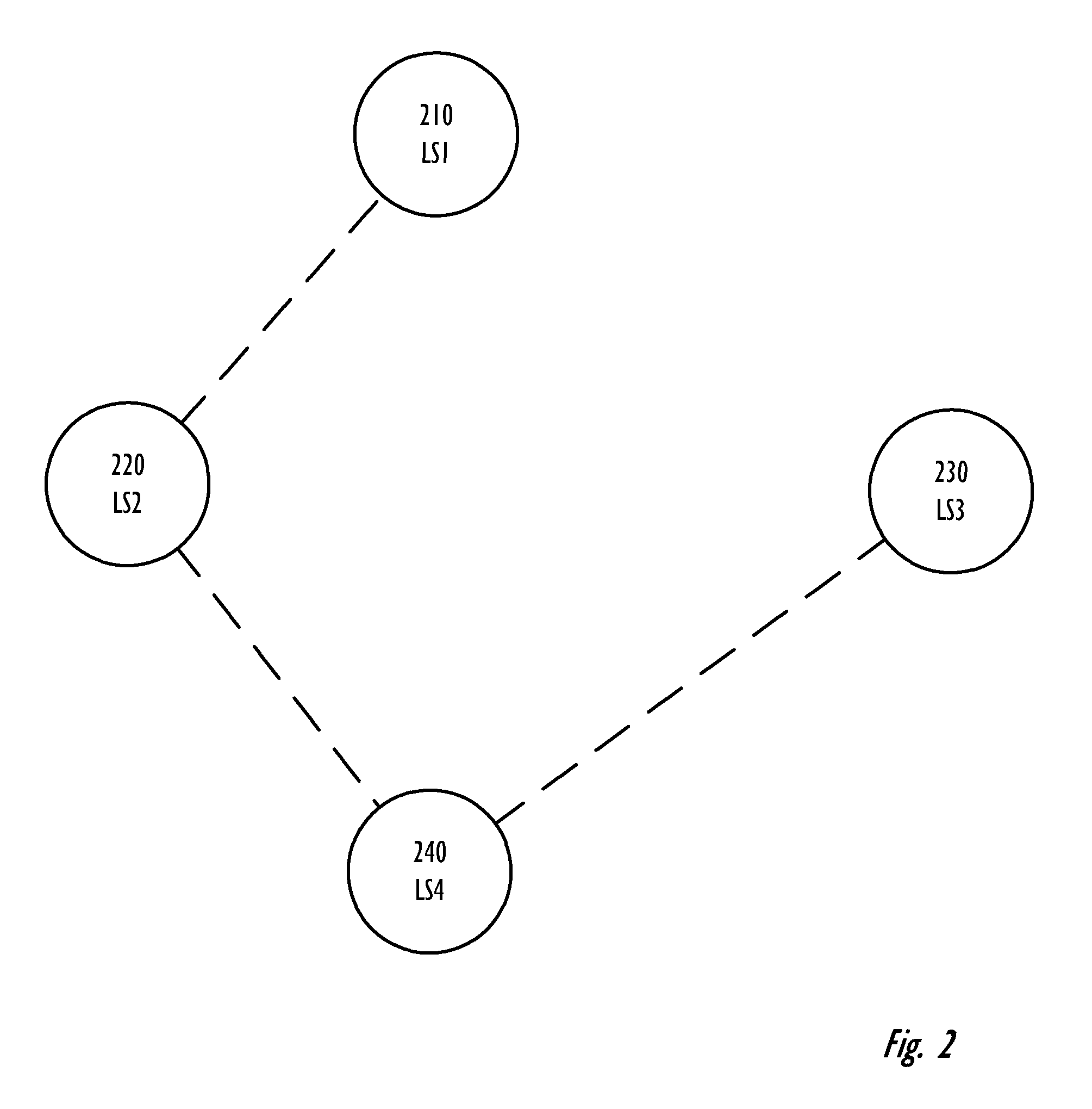
[0003]A Layer 2 network switch fabric is partitionable into a plurality of logical switches. Logical switches in multiple network switch chassis are connected by logical connections, such as logical inter-switch links, that use physical connections between physical switches, such as extended inter-switch links between base switches of their respective switch chassis, for data transport. Various embodiments provide techniques for determining a topology of logical connections among the logical switches. There are competing metrics for the topology, including robustness and scalability, which can result in different topologies. In addition, different switch operators may choose different balances between the competing metrics. Various embodiments provide for a topology factor that can vary the balance between some of the competing metrics, allowing variation in the creation of the topology of logical connections corresponding to the selected balance.

Problems solved by technology

Scalability of large Layer 2 (L2) fabrics has become a problem, as end users require ever-larger L2 fabrics, while also desiring consolidation of SAN islands and better tools for managing increasingly more complex SANs and other switch-based fabrics.

Method used


Image

  • Defining an optimal topology for a group of logical switches
  • Defining an optimal topology for a group of logical switches
  • Defining an optimal topology for a group of logical switches

Examples


Embodiment Construction

[0026]In the following description, for purposes of explanation, numerous specific details are set forth in order to provide a thorough understanding of the invention. It will be apparent, however, to one skilled in the art that the invention can be practiced without these specific details. In other instances, structure and devices are shown in block diagram form in order to avoid obscuring the invention. References to numbers without subscripts are understood to reference all instance of subscripts corresponding to the referenced number. Moreover, the language used in this disclosure has been principally selected for readability and instructional purposes, and may not have been selected to delineate or circumscribe the inventive subject matter, resort to the claims being necessary to determine such inventive subject matter.

[0027]Furthermore, although the following description is set forth in terms related to software, embodiments can be implemented in software, firmware, hardware, ...


PUM


Abstract

A Layer 2 network switch fabric is partitionable into a plurality of virtual fabrics. A network switch chassis is partitionable into a plurality of logical switches, each of which may be associated with one of the virtual fabrics, including a base switch. Logical switches in multiple network switch chassis are connected by logical connections, such as logical inter-switch links that use physical connections, such as extended inter-switch links between base switches, for data transport. A topology of logical connections is established that balances competing metrics, such as robustness and scalability, while maintaining alignment with the topology of the physical connections. A topology factor allows establishing different topologies with different balances between the competing metrics.

Description

TECHNICAL FIELD[0001]The present invention relates to the field of network fabric virtualization and in particular to defining logical connectivity among a plurality of logical switches defined on a plurality of physical switches.BACKGROUND ART[0002]Switch-based network fabrics have been a major part of the development of storage area networks (SANs) in modern networking environments. Scalability of large Layer 2 (L2) fabrics has become a problem, as end users require ever-larger L2 fabrics, while also desiring consolidation of SAN islands and better tools for managing increasingly more complex SANs and other switch-based fabrics.SUMMARY OF INVENTION[0003]A Layer 2 network switch fabric is partitionable into a plurality of logical switches. Logical switches in multiple network switch chassis are connected by logical connections, such as logical inter-switch links, that use physical connections between physical switches, such as extended inter-switch links between base switches of th...

Claims


Application Information

Patent Timeline
Patent Type & Authority Patents(United States)
IPC IPC(8): H04L12/28G06F15/177G06F15/173
CPCH04L45/583
Inventor GNANASEKARAN, SATHISH KUMARTADISINA, SHASHANK R.LAKSHMANAN, SUBRAMANIAN
Owner AVAGO TECH INT SALES PTE LTD
Why Eureka
Try Eureka