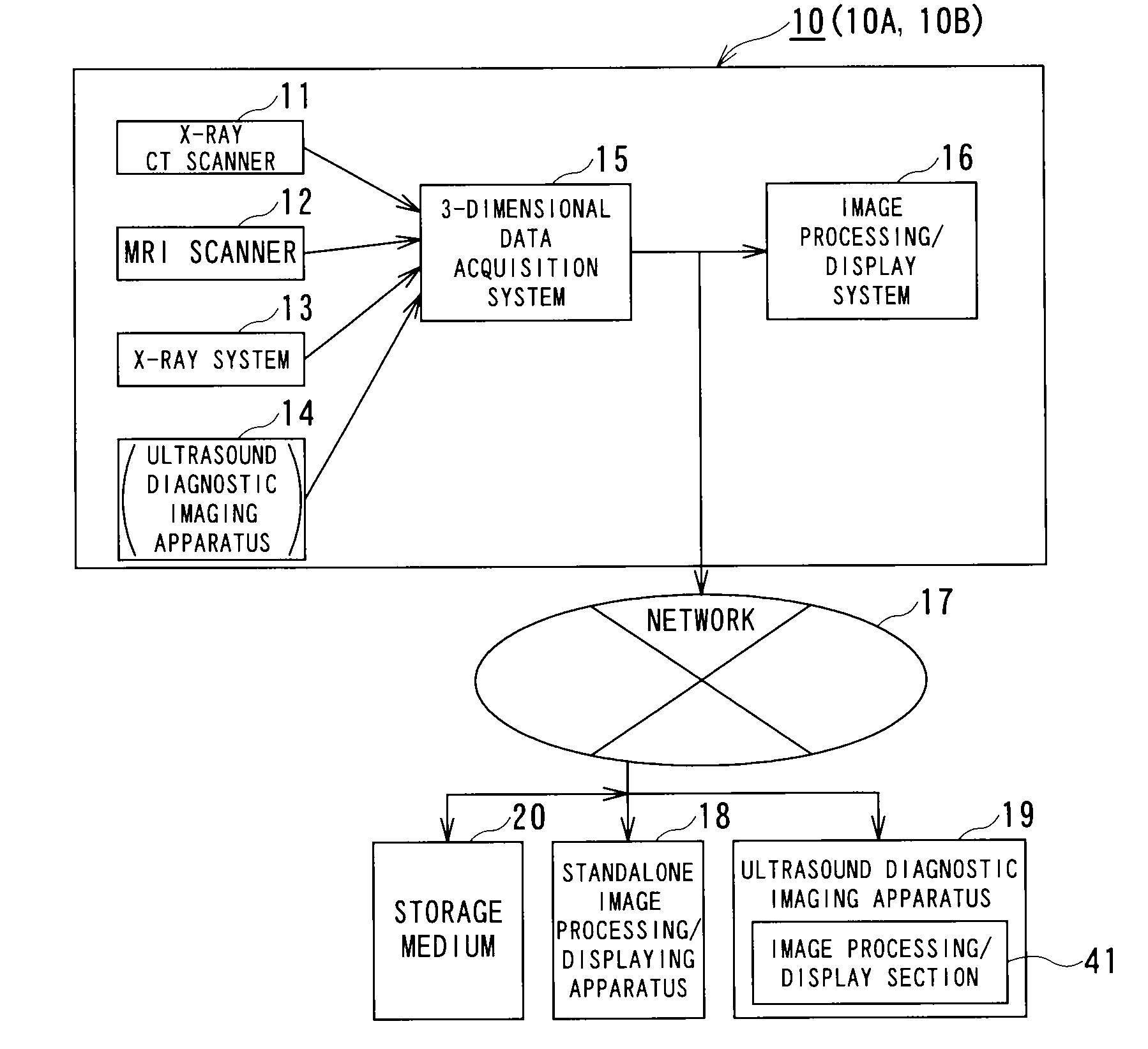
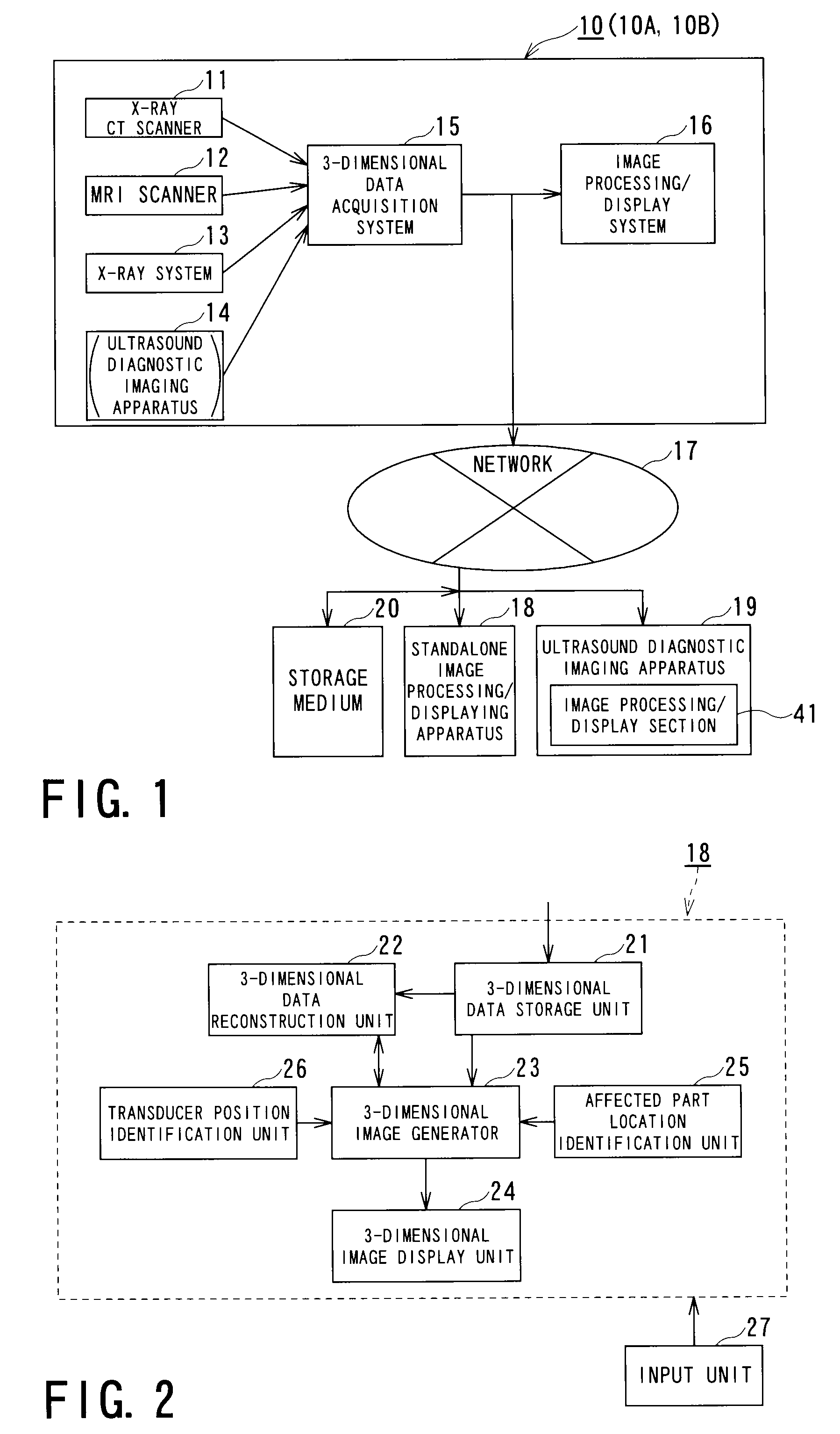
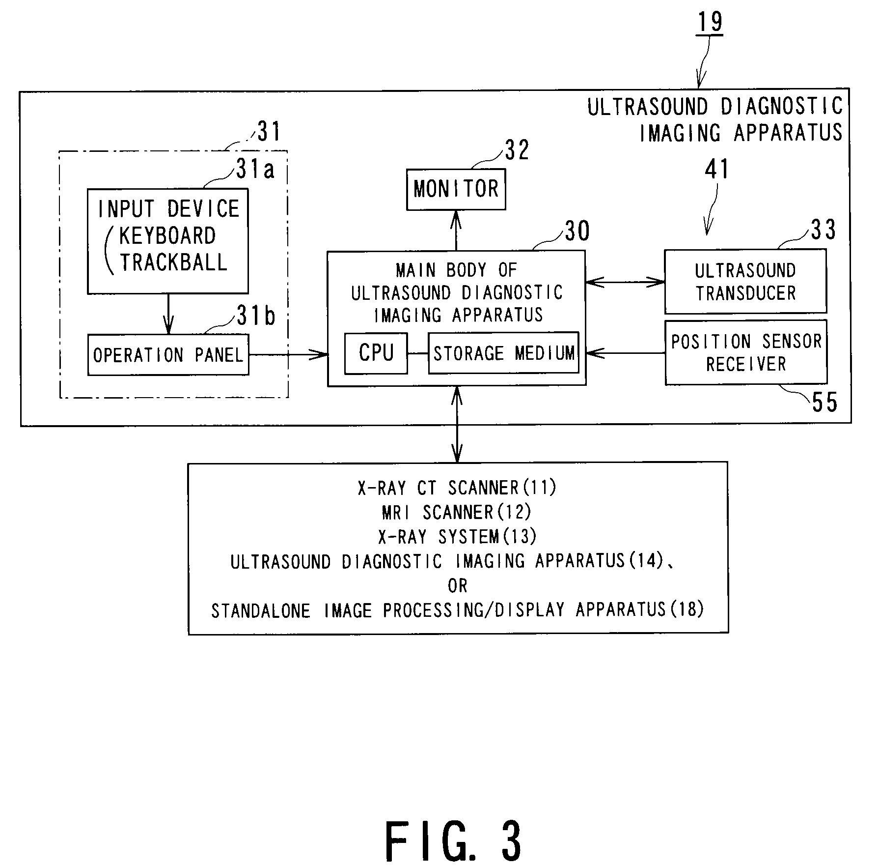
3-dimensional diagnostic imaging system
a diagnostic imaging and 3d technology, applied in the field of 3d diagnostic imaging systems, can solve the problems of increasing morbidity from liver cancer, inaccurate differential diagnosis, and ineffective use of 3-dimensional medical diagnostic images in planning or treating punctures or aftercare, so as to achieve accurate differential diagnosis and effectively identify the presence, size and content of the affected part.
- Summary
- Abstract
- Description
- Claims
- Application Information
AI Technical Summary
Benefits of technology
Problems solved by technology
Method used
Image
Examples
first embodiment
Modifications of First Embodiment
[0076]As illustrated in FIG. 9, in the first embodiment described above, the vector A (connecting the center locking point 39 and the feature point 40) in the 3-dimensional ultrasound image and the vector B (connecting the center locking point 49 and the feature point 50) in the 3-dimensional CT image are made coincident with each other and then, fine adjustment (by means of rotation) of a plane cut of the 3-dimensional CT image is made about the vector B serving as an axis so that images of the plane cuts of the 3-dimensional CT image and 3-dimensional ultrasound image are made coincident with each other. Since the plane cut of the 3-dimensional CT image is restrained by the vector B, this adjustment (rotation) is less cumbersome for the user and can relatively easily achieve coincidence between these images. Then, the plane cuts are locked upon coincidence therebetween. Since this locking function allows these plane cuts to be synchronously moved, ...
first modification
of First Embodiment
[0078]FIG. 10 illustrates an operational concept of a first modification of the first embodiment. In this first modification, after the vector A and the vector B are made coincident with each other, the correlation between the plane cut of the 3-dimensional CT image and that of the 3-dimensional ultrasound image is repeatedly calculated while the plane cut of the 3-dimensional CT image is being rotated about the vector B. Then, in the 3-dimensional CT image, a plane cut located at a position where the highest correlation is found is set as a plane cut that coincides with that of the 3-dimensional ultrasound image. The subsequent processing is the same as that of the first embodiment.
second modification
of First Embodiment
[0079]FIG. 11 illustrates an operational concept of a second modification of the first embodiment. The second modification further advances the concept of the first modification in that although the vectors A and B are made coincident with each other in the first modification, only the center locking point 39 and the center locking point 49 are made coincident in the second modification. Next, the correlation between the plane cut of the 3-dimensional CT image and that of the 3-dimensional ultrasound image is repeatedly calculated while the plane cut of the 3-dimensional CT image is being rotated about the center locking point 49 (i.e., rotated about two independent axes). Then, in the 3-dimensional CT image, a plane cut located at a position where the highest correlation is found is set as a plane cut that coincides with that of the 3-dimensional ultrasound image. The subsequent processing is the same as that of the first embodiment. Although the calculation load...
PUM
 Abstract
Description
Claims
Application Information
 - R&D
- Intellectual Property
- Life Sciences
- Materials
- Tech Scout
- Unparalleled Data Quality
- Higher Quality Content
- 60% Fewer Hallucinations
Browse by: Latest US Patents, China's latest patents, Technical Efficacy Thesaurus, Application Domain, Technology Topic, Popular Technical Reports.
© 2025 PatSnap. All rights reserved.Legal|Privacy policy|Modern Slavery Act Transparency Statement|Sitemap|About US| Contact US: help@patsnap.com


