
3-dimensional diagnostic imaging system

Inactive Publication Date: 2008-12-04
TOSHIBA MEDICAL SYST CORP
View PDF11 Cites 38 Cited by
  • Summary
  • Abstract
  • Description
  • Claims
  • Application Information

AI Technical Summary

Benefits of technology

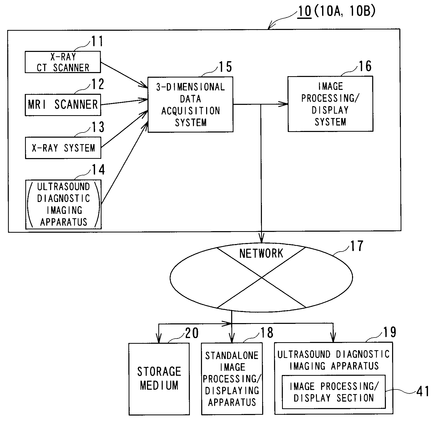
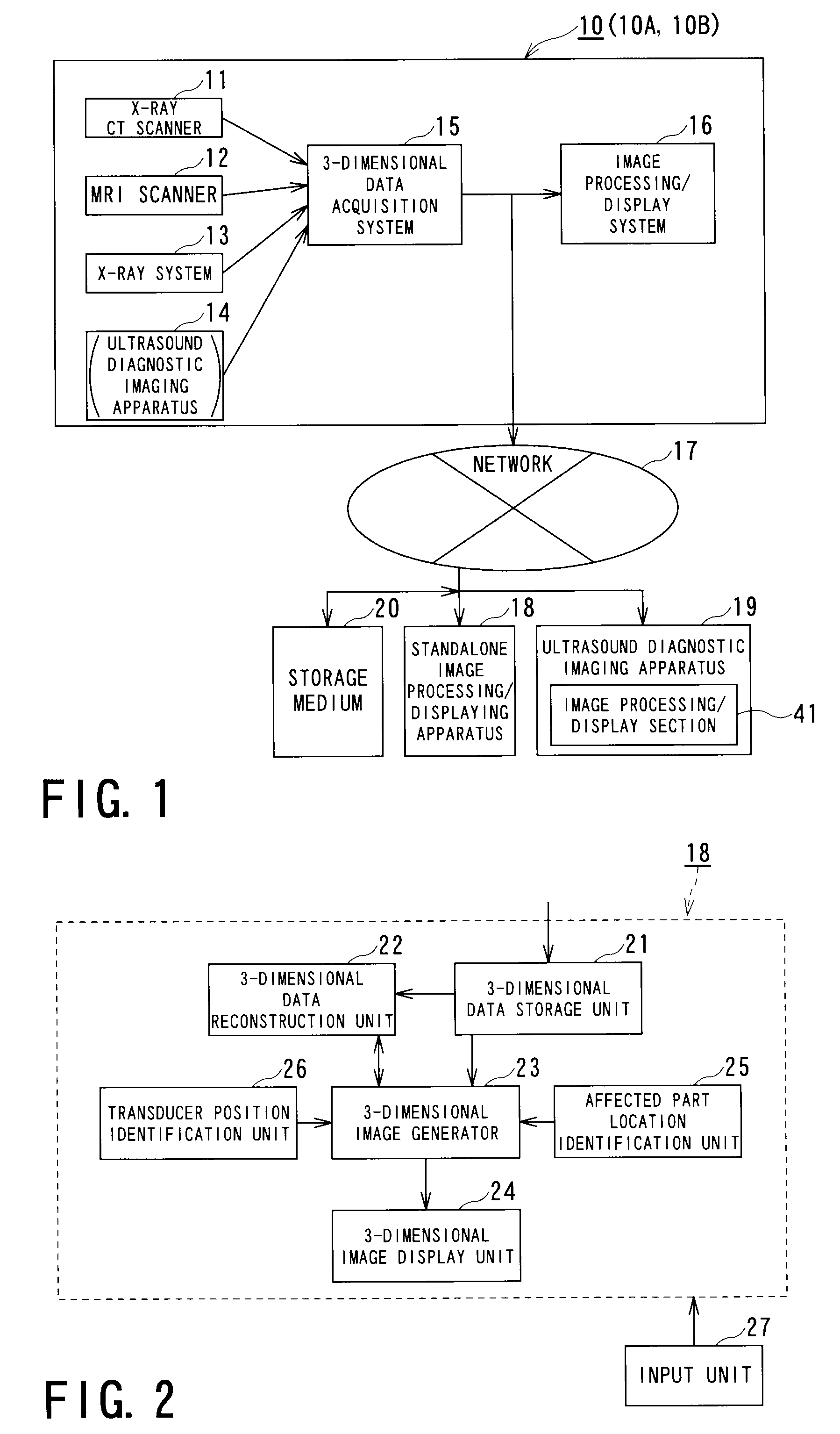
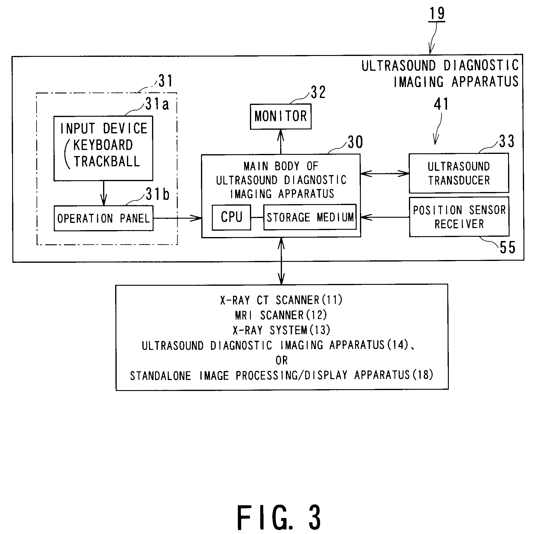
[0016]The present invention has been made in view of the circumstances described above. An object of the present invention is to provide a 3-dimensional diagnostic imaging system which allows comparison of any cross sections between a 3-dimensional ultrasound image and a 3-dimensional diagnostic modality image for complementary purposes, and thus makes it possible to perform effective and efficient detection and differential diagnosis of a disease, such as cancer.
[0017]Another object of the present invention is to provide a 3-dimensional diagnostic imaging system which allows easy and simple comparison of cross sections between a local ultrasound image and an overall 3-dimensional diagnostic modality image for complementary purposes, by using a 3-dimensional ultrasound image and without using a cross-sectional image that can be acquired only at a position which allows acquisition of an image with an ultrasound transducer.
[0019]In diagnosis and evaluation of therapeutic effects using a 3-dimensional ultrasound image acquired by an ultrasound diagnostic imaging apparatus, the 3-dimensional diagnostic imaging system of the present invention allows the user to refer to a 3-dimensional diagnostic modality image (3-dimensional reference image) acquired by a medical diagnostic imaging modality other than the ultrasound diagnostic imaging apparatus, and make a simple comparison of common cross sections between the 3-dimensional ultrasound image and the 3-dimensional reference image, which are complementary to each other. The 3-dimensional diagnostic imaging system of the present invention also allows a simple comparison of common cross sections between 3-dimensional diagnostic modality images of different time phases. Thus, the user can reliably, efficiently, and effectively identify the presence, size, and content of a part affected with cancer or the like and make an accurate differential diagnosis.

Problems solved by technology

In particular, liver cancer represents about 10% of all cancer diseases and unfortunately, the mortality from liver cancer is increasing.
However, despite the recent technological advances in 3-dimensional diagnostic imaging and therapeutic / diagnostic puncture, 3-dimensional medical diagnostic images are not effectively used in planning or treatment of puncture or in aftercare.
Ultrasound images used in clinical practice are local diagnostic images which do not allow simultaneous observation of the entire liver and adjacent parts, such as a diaphragm and the like.
However, with this assisting apparatus, it is difficult to determine whether there is an obstacle on or near the path along which to insert a puncture needle.
In a technique for displaying a virtual ultrasound cross-sectional image superimposed on a 3-dimensional CT image, there is a problem in that a part to be treated can be seen only on an X-ray CT image and cannot be seen or cannot be easily seen on an ultrasound diagnostic image.
Another problem is that if there are two or more parts to be treated, it is difficult to perform effective treatment on the basis only of images obtained in planning of treatment.
Therefore, it is difficult to make comparison, after treatment, among images acquired by different modalities.

Method used


Image

  • 3-dimensional diagnostic imaging system
  • 3-dimensional diagnostic imaging system
  • 3-dimensional diagnostic imaging system

Examples


first embodiment

Modifications of First Embodiment

[0076]As illustrated in FIG. 9, in the first embodiment described above, the vector A (connecting the center locking point 39 and the feature point 40) in the 3-dimensional ultrasound image and the vector B (connecting the center locking point 49 and the feature point 50) in the 3-dimensional CT image are made coincident with each other and then, fine adjustment (by means of rotation) of a plane cut of the 3-dimensional CT image is made about the vector B serving as an axis so that images of the plane cuts of the 3-dimensional CT image and 3-dimensional ultrasound image are made coincident with each other. Since the plane cut of the 3-dimensional CT image is restrained by the vector B, this adjustment (rotation) is less cumbersome for the user and can relatively easily achieve coincidence between these images. Then, the plane cuts are locked upon coincidence therebetween. Since this locking function allows these plane cuts to be synchronously moved, ...

first modification

of First Embodiment

[0078]FIG. 10 illustrates an operational concept of a first modification of the first embodiment. In this first modification, after the vector A and the vector B are made coincident with each other, the correlation between the plane cut of the 3-dimensional CT image and that of the 3-dimensional ultrasound image is repeatedly calculated while the plane cut of the 3-dimensional CT image is being rotated about the vector B. Then, in the 3-dimensional CT image, a plane cut located at a position where the highest correlation is found is set as a plane cut that coincides with that of the 3-dimensional ultrasound image. The subsequent processing is the same as that of the first embodiment.

second modification

of First Embodiment

[0079]FIG. 11 illustrates an operational concept of a second modification of the first embodiment. The second modification further advances the concept of the first modification in that although the vectors A and B are made coincident with each other in the first modification, only the center locking point 39 and the center locking point 49 are made coincident in the second modification. Next, the correlation between the plane cut of the 3-dimensional CT image and that of the 3-dimensional ultrasound image is repeatedly calculated while the plane cut of the 3-dimensional CT image is being rotated about the center locking point 49 (i.e., rotated about two independent axes). Then, in the 3-dimensional CT image, a plane cut located at a position where the highest correlation is found is set as a plane cut that coincides with that of the 3-dimensional ultrasound image. The subsequent processing is the same as that of the first embodiment. Although the calculation load...


PUM


Abstract

A 3-dimensional diagnostic imaging system for acquiring and displaying 3-dimensional images includes an ultrasound diagnostic imaging apparatus configured to display any cross section of a 3-dimensional image extracted from volume data including an affected part of a subject; a 3-dimensional medical diagnostic imaging apparatus configured to display a cross section of a 3-dimensional image extracted from volume data obtained by medical diagnostic imaging modalities other than the ultrasound diagnostic imaging apparatus, the cross section being substantially identical to the cross section displayed by the ultrasound diagnostic imaging apparatus; and an image processing / display unit configured to synchronously display substantially identical cross sections of a plurality of 3-dimensional images from both the ultrasound diagnostic imaging apparatus and the 3-dimensional medical diagnostic imaging apparatus, or to synchronously display substantially identical cross sections of a plurality of 3-dimensional images extracted from volume data obtained by the same medical diagnostic imaging modality at different times.

Description

BACKGROUND OF THE INVENTION[0001]1. Field of the Invention[0002]The present invention relates to imaging technology for diagnosis based on 3-dimensional (3D) medical images, and particularly relates to a 3-dimensional diagnostic imaging system for use in locating an affected part and making a differential diagnosis using a 3-dimensional ultrasound image and another type of 3-dimensional diagnostic modality image in a complementary manner.[0003]2. Description of the Related Art[0004]Cancer is one of three major diseases in Japan today. Of the three major diseases, cancer is the only disease with an increasing mortality. Accordingly, there are strong social demands for improved treatment as well as diagnosis of cancer. In particular, liver cancer represents about 10% of all cancer diseases and unfortunately, the mortality from liver cancer is increasing.[0005]As for diagnosis of liver cancer, early detection has been made possible by recent technological advances in medical diagnostic...

Claims


Application Information

Patent Timeline
IPC IPC(8): A61B8/00
CPCA61B6/032G06T2219/2004A61B6/466A61B6/5247A61B8/0833A61B8/13A61B8/4245A61B8/483A61B8/5238G01S7/52074G01S7/52084G01S15/899G01S15/8993G06F19/321G06T19/00G01S15/8915G01S15/8929G06T2219/028A61B6/12A61B8/4254G16H30/20G16H50/20
Inventor YAMAGATA, HITOSHI
Owner TOSHIBA MEDICAL SYST CORP
Learn More