Optical transmission system

a transmission system and optical repeater technology, applied in the field of optical repeater devices, can solve the problems of inability to transmit signals to the same olt, inability to maintain transmission throughput, and large time and cost of exchanging an existing olt, so as to reduce the cost of system change and maintain transmission throughput without decreasing

Active Publication Date: 2012-12-25
FURUKAWA ELECTRIC CO LTD
View PDF22 Cites 4 Cited by
  • Summary
  • Abstract
  • Description
  • Claims
  • Application Information

AI Technical Summary

Benefits of technology

[0028]An object of the present invention is to provide an optical repeater device (ORD) and an optical transmission system of long distance transmission possible, with keeping a transmission throughput without decreasing, and with being able to reducing the cost for system change.
[0043]According to the present invention, both of a central office side optical repeater device (ORD) and a user side ORD have a wavelength division multiplexing (WDM) function respectively. And then using an existing user side optical network unit (ONU) and an existing central office side optical line terminal (OLT), a transmission becomes possible with the existing wavelength as the standard band thereof. Therefore, with using the existing specified side OLT and the user side ONU without changing any, the long distance communication becomes possible to be realized.
[0044]Moreover, regarding the user side ORD, functions are provided therein, that a preamble signal included in a burst signal is to be deleted, and then another preamble signal is to be added onto before and / or after a normal data. Thus, a decrease of the throughput for data transmission, due to a disappearance of the preamble signals occurred in ordinary repeaters, becomes able to be prevented.
[0045]Furthermore, for a gap between any neighboring pair of the burst signals output from the user side ONU, a preamble signal is to be added in the preamble compensating circuit, and then the signal is to be output as a continuous signal therefrom. Therefore, for subsequent components from then onward, a low cost component becomes possible to be used, because of not for burst signals but for continuous signals.
[0047]Moreover, for the gap between any neighboring pair of the burst signals output from the user side ONU, the preamble signal is to be added in the preamble compensating circuit, and then the signal is to be output as the continuous signal therefrom. Thus, for the subsequent components from then onward, the low cost component becomes possible to be used, because of not for burst signals but for continuous signals.
[0048]Moreover, according to the present invention, for both sides of the central office side and the user side, the ORDs having the WDM function corresponding to optical signals are connected respectively thereto. And then with using the existing user side ONU and the existing central office side OLT, the transmission becomes possible with the existing wavelength as the standard band thereof. Therefore, with using the existing specified central office side OLT and the existing specified user side ONU without changing any, the long distance communication becomes possible to be realized. Especially, in the case of wavelength multiplexed transmitting, different from other technologies, an optical transmission module for burst signals becomes unnecessary, which corresponds to each wavelength thereof. Therefore, a module for general purpose, such as an optical transmission module for coarse wavelength division multiplexing (CWDM), an optical transmission module for dense wavelength division multiplexing (DWDM), or the like, becomes possible to be used thereby.

Problems solved by technology

A first problem is that a load of time and cost for exchanging an existing OLT is quite large, due to realizing impossible with using the existing OLT regarding the optical transmission system according to the patent document 1 and the nonpatent document 1.
However, essentially such the existing OLT is not suitable for exclusive use of WDM transmission.
A second problem is that, regarding the PDS type system of time division multiplex (TDM), such as the G-PON, the GE-PON, or the like, from a plurality of ONUs connected with single splitter, signals are not able to be transmitted to the OLT at the same time.
Hence, a certain amount of time is required for such the process.
Therefore, in the case of taking time for regenerating the data and the clock too short, the data and the clock cannot help but be regenerated properly.
As above mentioned, in the case of using the wavelength converter as a repeater, with such the ordinary methods, at least a part of the preamble signal cannot help but be disappeared.
Hence, a transmission capacity (throughput) as a total system cannot help but be decreased.
A third problem is that, according to the patent document 1 and the nonpatent document 1, the upward burst signal from the ONU to the OLT is to be directly relayed, as the system.
And then the cost for the total system cannot help but be increased.

Method used


Image

  • Optical transmission system
  • Optical transmission system
  • Optical transmission system

Examples


first embodiment

[0094]The First Embodiment

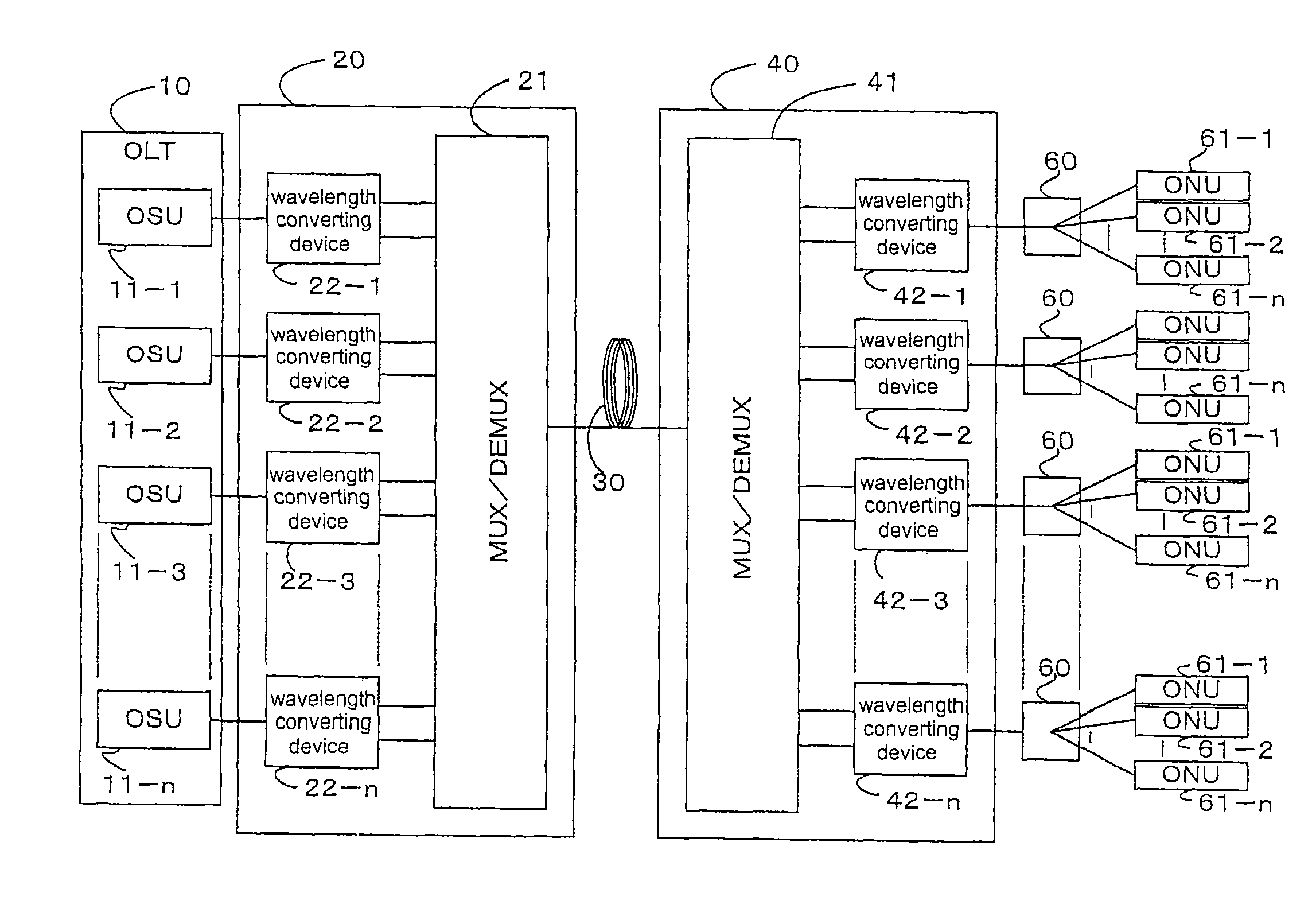
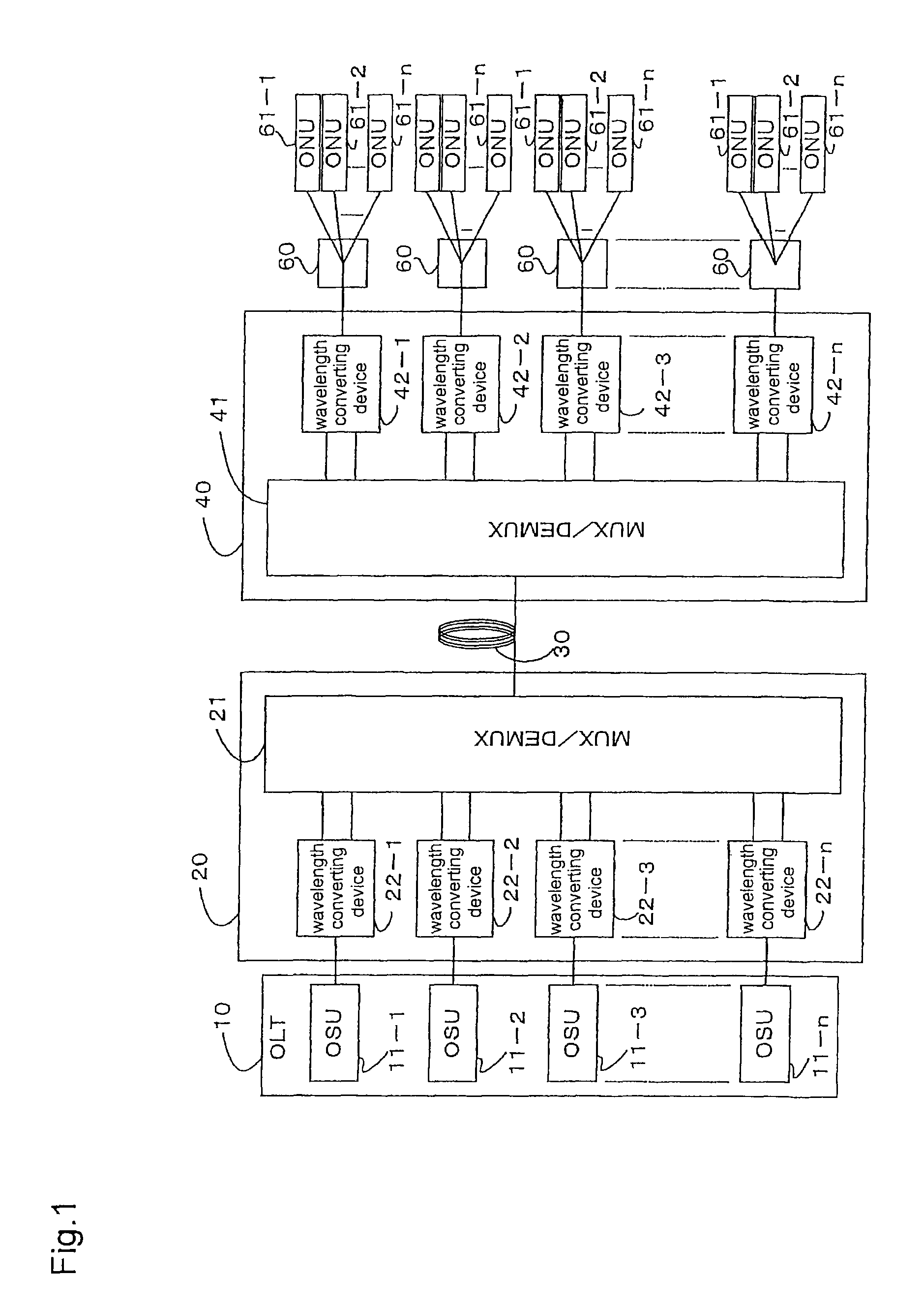
[0095]FIG. 1 is a diagram showing a configuration of a PDS type optical transmission system regarding the first embodiment of the present invention.

[0096]In FIG. 1, optical subscriber units (OSUs) 11-1, 11-2 to 11-n provided inside a center side optical line terminal (OLT) 10 compliant with such as the G-PON, the GE-PON, or the like, are connected with a plurality of user side optical network units (ONUs) 61-1, 61-2, to 61-n respectively, via a central office side optical repeater device (ORD) 20, an optical transmission path 30, a user side ORD 40, and an optical coupler (a splitter) 60. Moreover, any one of such the ONUs 61-1, 61-2, to 61-n comprises a configuration compliant with the G-PON, the GE-PON, or the like.

[0097]Moreover, the central office side ORD 20 comprises wavelength converting devices 22-1, 22-2, 22-n to be connected with each OSU 11-1, 11-2, 11-n respectively, and a multiplexer / de-multiplexer (MUX / DEMUX) 21 to be connected with such the w...

second embodiment

[0146]The Second Embodiment

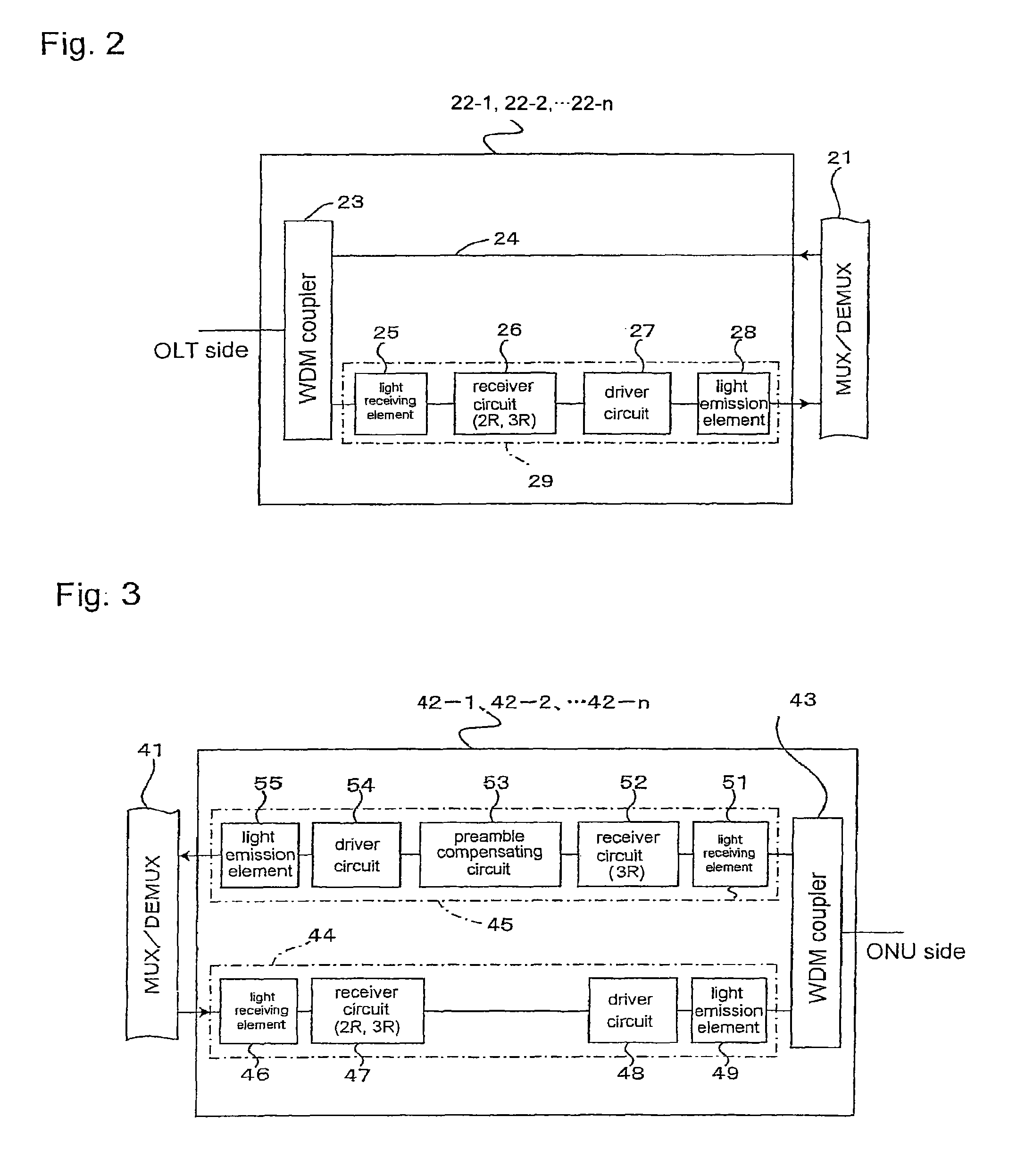
[0147]FIG. 7 is a circuit block diagram showing a wavelength converting device to be comprised of a user side ORD used for a PDS type optical transmission system regarding the second embodiment of the present invention, wherein a symbol similar to that in FIG. 3 shows the similar element.

[0148]That is to say, FIG. 7 shows a configuration of any one of the wavelength converting devices 42-1, 42-2 to 32-n in the user side ORD 40 used for the optical transmission system shown in FIG. 1. As different from FIG. 3, it comprises a configuration that there is no preamble compensating circuit 53 in the up transmission system circuit 45a.

[0149]Hence, a preamble signal included in a upward burst signal output from any one of the ONUs 61-1, 61-2 to 61-n is not to be compensated. Moreover, without converting the burst signal into a continuous signal, the signal is to be processed for the 2R or the 3R in the receiver circuit 52.

[0150]Such the wavelength converting devi...

third embodiment

[0152]The Third Embodiment

[0153]FIG. 8 is a circuit block diagram showing an ORD to be connected with an optical transmission path for a burst signal including a preamble signal in such as an optical transmission system regarding the third embodiment of the present invention, wherein a symbol similar to that in FIG. 3 shows the similar element.

[0154]In FIG. 8, an optical repeater device (ORD) 42 comprises the similar configuration to the up transmission system circuit 45 in any one of the wavelength converting devices 42-1, 42-2 to 42-n provided in the user side ORD 40 in FIG. 1. That is to say, it comprises the configuration that, the light receiving element 51, the receiver circuit 52, the preamble compensating circuit 53, the driver circuit 54 and the light emission element 55 are connected in order toward the optical signal transmission direction therebetween.

[0155]Such the ORD 42 is not limited to be used as the user side ORD 40 shown in FIG. 1. And, with compensating a disappe...


PUM


Abstract

An optical transmission system is provided. The optical transmission system includes a user side optical repeater device, a central office side optical repeater device, and wavelength multiplexing and wavelength de-multiplexing functions. The user side optical repeater device is to be connected with a user side optical network unit, transmits data in two ways, and is used for wavelength division multiplexing. The central office side optical repeater device is to be connected with a central office side optical line terminal, transmits data in two ways, and is used for wavelength division multiplexing. The wavelength multiplexing and wavelength de-multiplexing functions are used for relaying between the user side optical repeater device and the central office side optical repeater device.

Description

CROSS-REFERENCE TO RELATED APPLICATIONS[0001]This application is a continuation of U.S. patent application Ser. No. 12 / 046,069, filed Mar. 11, 2008, the entire content of which is incorporated herein by reference, and which is a continuation of PCT / JP2006 / 324551 filed Dec. 8, 2006, which claims priority to Japanese Application Nos. JP2005-355928, filed Dec. 9, 2005; JP2005-355929, filed Dec. 9, 2005; and JP2006-253771, filed Sep. 20, 2006.BACKGROUND OF THE INVENTION[0002]1. Field of the Invention[0003]The present invention relates to an optical repeater device (ORD) and an optical transmission system. More specifically, it relates to the ORD, and to an optical transmission system of a passive double star (PDS) type comprising a repeater of the ORD.[0004]2. Description of the Related Art[0005]Regarding an optical network, such as a fiber to the home (FTTH), a cable television (CATV), and the like, an optical transmission system of a passive double star (PDS) type is used, in which a ...

Claims


Application Information

Patent Timeline
Patent Type & Authority Patents(United States)
IPC IPC(8): H04J14/00H04B10/27H04B10/272H04B10/29
CPCH04B10/27H04B10/272H04J14/0278H04B10/29H04B2210/258
Inventor MIURA, MASAYUKI
Owner FURUKAWA ELECTRIC CO LTD
Why Eureka
Try Eureka