
Image forming apparatus

a technology of image forming apparatus and forming node, which is applied in the direction of error detection/correction, instruments, electrographic process, etc., can solve the problems of error detection, conventional techniques, and the need for monitoring-dedicated nodes, and achieve the effect of increasing the error detection accuracy of each control uni

Inactive Publication Date: 2012-12-25
CANON KK
View PDF16 Cites 1 Cited by
  • Summary
  • Abstract
  • Description
  • Claims
  • Application Information

AI Technical Summary

Benefits of technology

[0009]The present invention enables realization of an image forming apparatus which adopts a distributed control system and increases the error detection accuracy of each control unit.

Problems solved by technology

However, in the distributed control system, an error needs to be detected strictly to normally operate a plurality of boards (CPUs) in collaboration with each other, unlike centralized control.
However, these conventional techniques suffer the following problems.
However, a monitoring-dedicated node is required and raises the cost.
In a system having a hierarchical structure, it is difficult to specify a concrete trouble part when a trouble is determined using only the traffic of an upper layer.
However, when the test mode is applied to an image forming apparatus, the contents of the test are limited upon generation of a paper jam by a trouble during operation.
Further, it is difficult to detect a trouble part in the test mode upon generation of a dynamic timing error or in an emergency stop process during operation.

Method used


Image

  • Image forming apparatus
  • Image forming apparatus
  • Image forming apparatus

Examples


first embodiment

[0027]

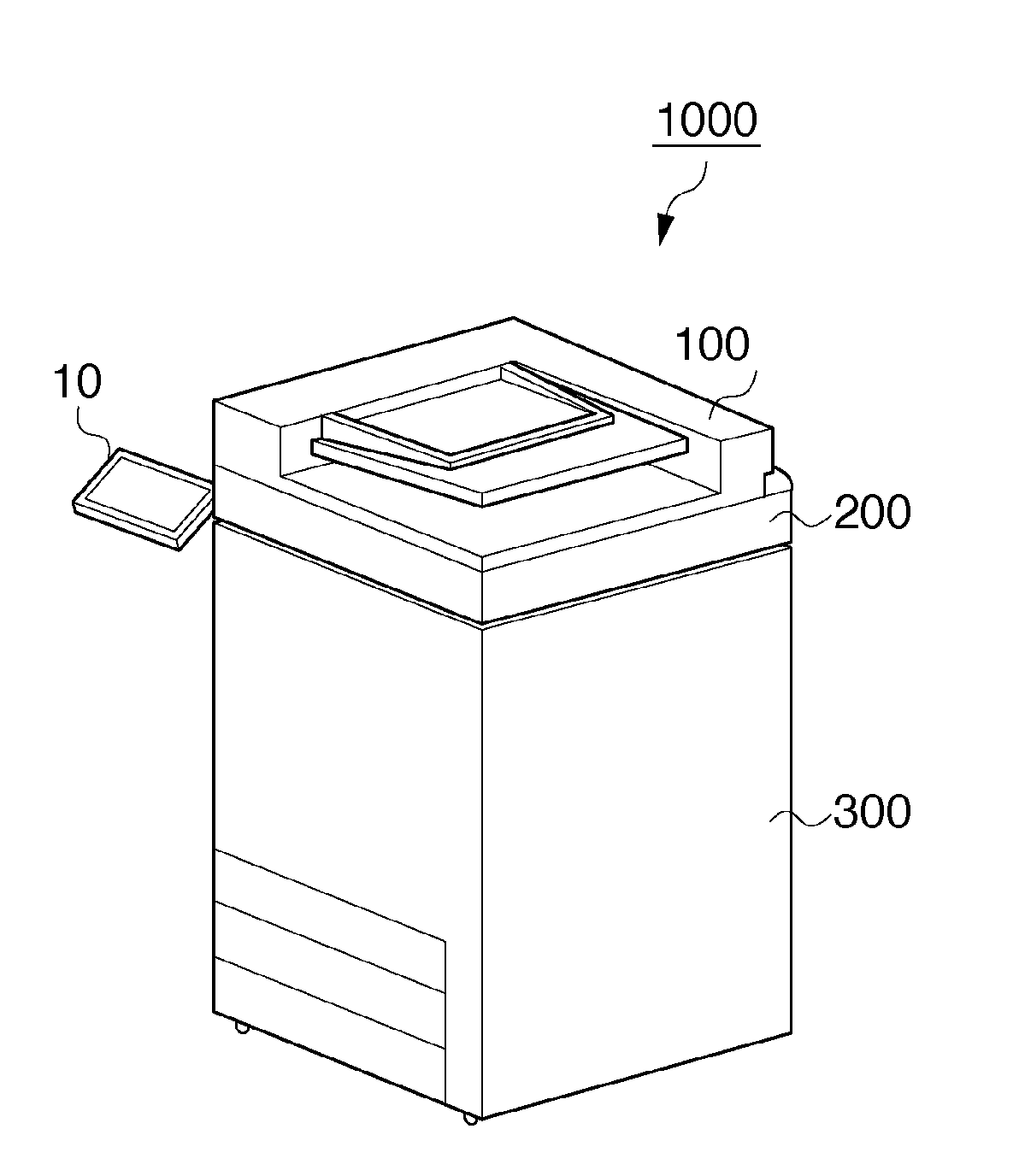
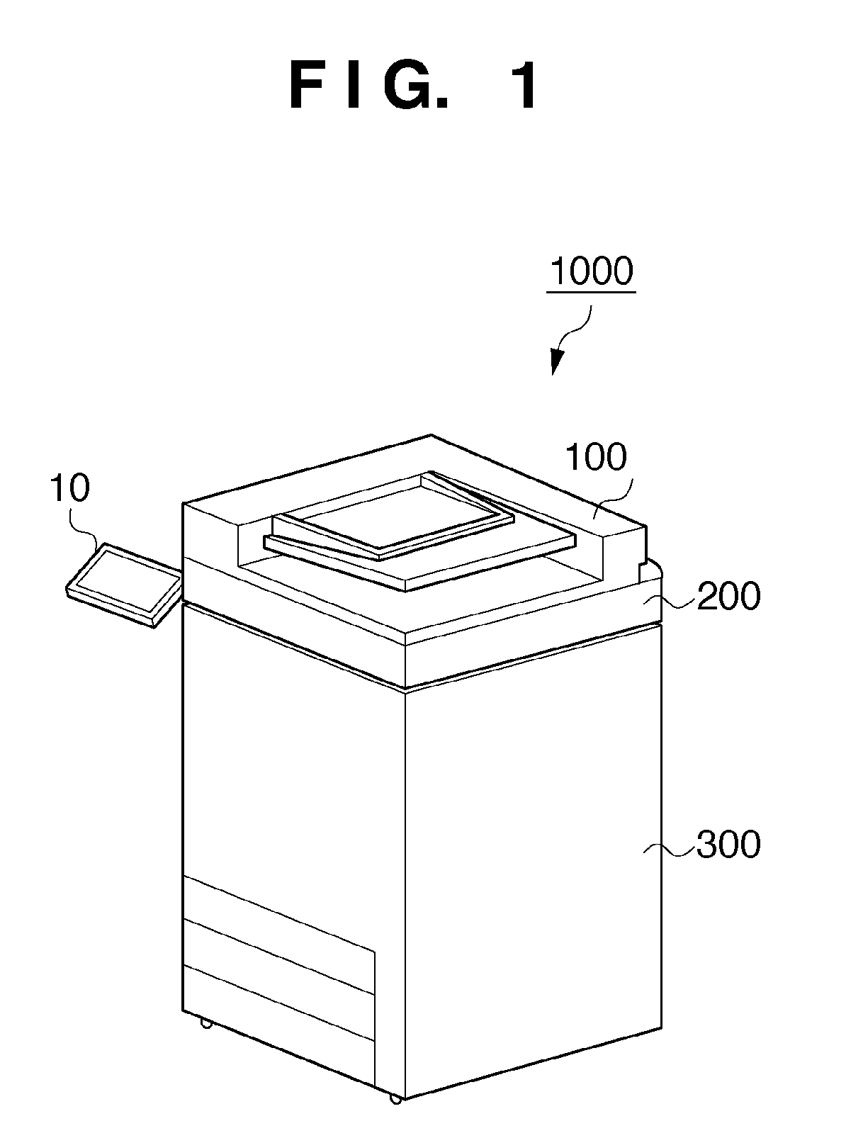
[0028]The first embodiment will be described below with reference to FIGS. 1 to 13. FIG. 1 is a perspective view showing an overview of an image forming apparatus 1000 according to the first embodiment.

[0029]The image forming apparatus 1000 includes an automatic document feeder (DF) 100, image reading unit 200, image forming unit 300, and operation unit 10. As shown in FIG. 1, the image reading unit 200 is mounted on the image forming unit 300. The automatic document feeder 100 is mounted on the image reading unit 200. The image forming apparatus 1000 implements distributed control using a plurality of control units (CPUs). The arrangement of each CPU will be described later with reference to FIG. 3.

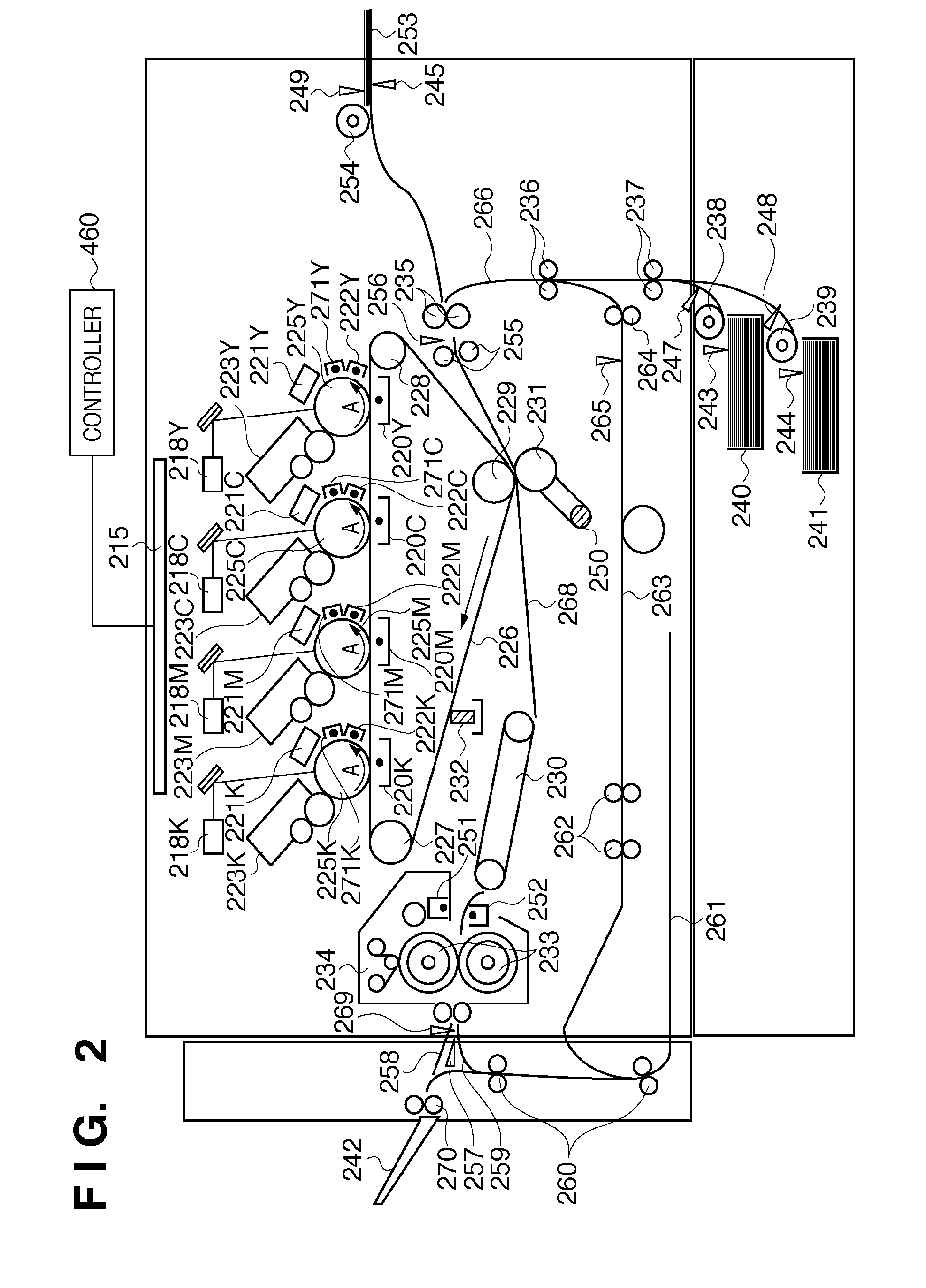
[0030]The automatic document feeder 100 automatically conveys a document onto a document glass. The image reading unit 200 outputs image data by reading the document conveyed from the automatic document feeder 100. The image forming unit 300 forms an image on a printing material ba...


PUM


Abstract

There is provided an image forming apparatus which adopts a distributed control system and increases the error detection accuracy of each control unit. To accomplish this, the image forming apparatus includes a master control unit that controls the overall image forming apparatus, a plurality of sub-master control units that control a plurality of functions for performing image formation, and a plurality of slave control units that control loads for implementing a plurality of functions. The master control unit determines a diagnosis path for performing a diagnosis process for an error using the signal lines and a connection bridge connected to the respective control units. The master control unit performs the diagnosis process for an error in accordance with the determined diagnosis path.

Description

BACKGROUND OF THE INVENTION[0001]1. Field of the Invention[0002]The present invention relates to an image forming apparatus implemented by a distributed control system including a plurality of CPU groups having a hierarchical structure.[0003]2. Description of the Related Art[0004]Centralized control using one CPU is performed for printer device control of an image forming apparatus using an electrophotographic system. An increasing CPU load due to centralized control requires a higher performance CPU. In addition, as the load of the printer device rises, a bundle of control communication lines needs to be laid from a CPU board to distant load driver units and many long control communication lines are indispensable. To solve these problems, a control form is receiving a great deal of attention, in which control modules which build an electrophotographic system are assigned to sub-CPUs.[0005]Examples of the construction of a control system by distributing respective partial module con...

Claims


Application Information

Patent Timeline
Patent Type & Authority Patents(United States)
IPC IPC(8): G06F11/00
CPCG03G15/50
Inventor OTANI, ATSUSHIHATA, SHIGEOSAKAI, AKIHIKOTAKEDA, SHOJIYAMAMOTO, SATORUTAKAHASHI, KEITASEKI, HIROTAKA
Owner CANON KK
Learn More