Multifunction wiper blade connector and assembly

a multi-functional, wiper blade technology, applied in the direction of vehicle maintenance, vehicle cleaning, domestic applications, etc., can solve the problems of unintended disconnection of the wiper blade, unexpected disassembly of the wiper arm, and use of self-locking retention features, etc., to achieve convenient attachment points

Active Publication Date: 2013-01-01
FEDERAL MOGUL MOTORPARTS LLC
View PDF29 Cites 25 Cited by
  • Summary
  • Abstract
  • Description
  • Claims
  • Application Information

AI Technical Summary

Benefits of technology

[0011]A connector according to this invention provides a convenient attachment point for a variety of wiper arm end designs without the need for auxiliary or supplemental adapter components. When attaching some hook style arm configurations, the connector does not require the blade to be placed in a service up condition. Furthermore, the connector of this invention can be implemented as a low profile design which is resistant to impact damages and therefore securely retains the wiper blade to the wiper arm.

Problems solved by technology

The connector is largely exposed to the environment and if damaged may lead to unintended disconnection of the wiper blade.
For example, impact by a foreign object such as a stone thrown by a passing car or an ice scraper can conceivably cause the connector to release its otherwise secure engagement with the wiper blade, resulting in unexpected disassembly from the wiper arm.
Another disadvantage inherent in prior art connector designs resides in the self-locking retention features used by 9×3 and 9×4 hook ends on a wiper arm.
It will be appreciated that not all vehicle wiper assemblies include a convenient service up position and therefore changing the wiper blades on hook style arms can be difficult.

Method used


Image

  • Multifunction wiper blade connector and assembly
  • Multifunction wiper blade connector and assembly
  • Multifunction wiper blade connector and assembly

Examples


Embodiment Construction

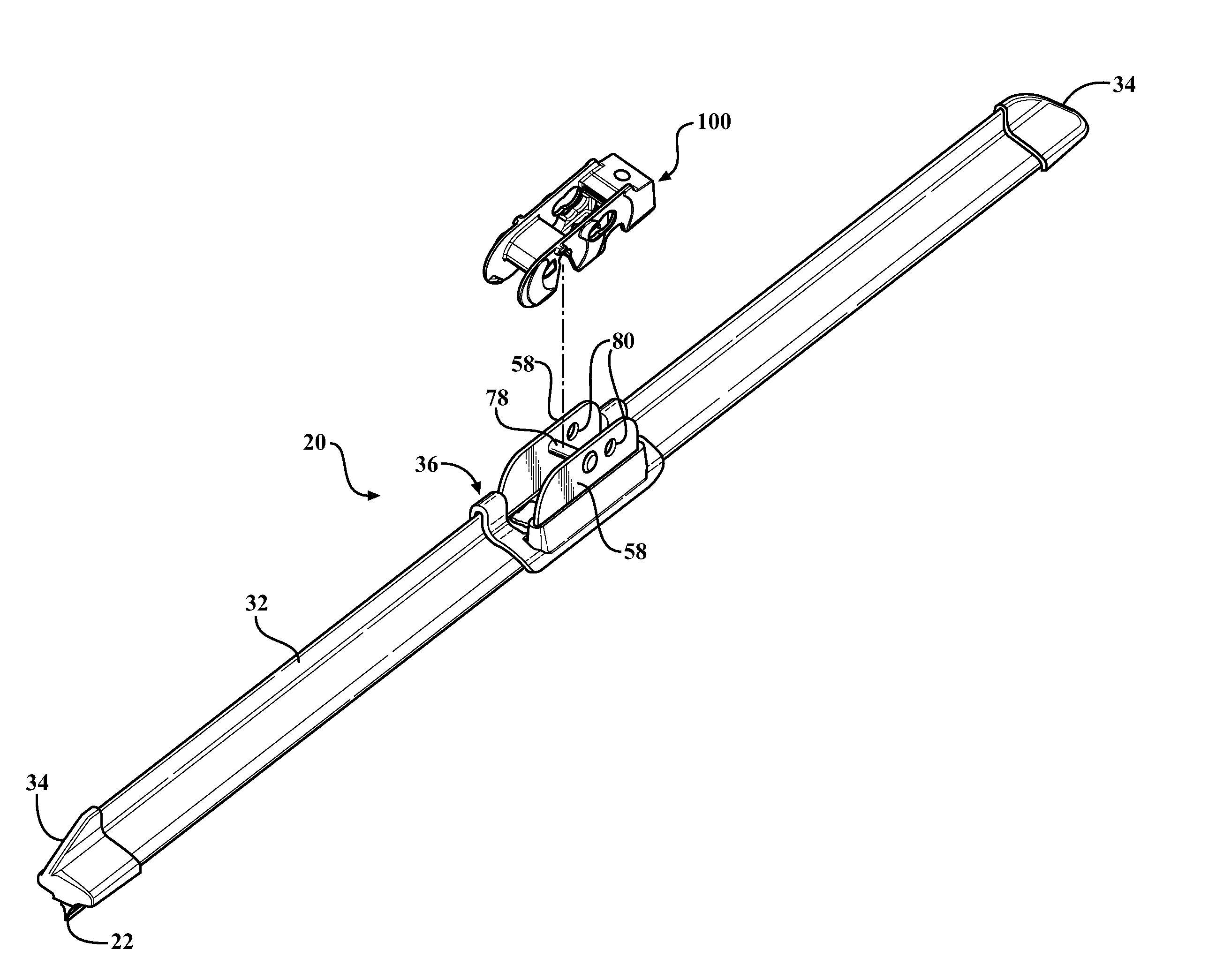
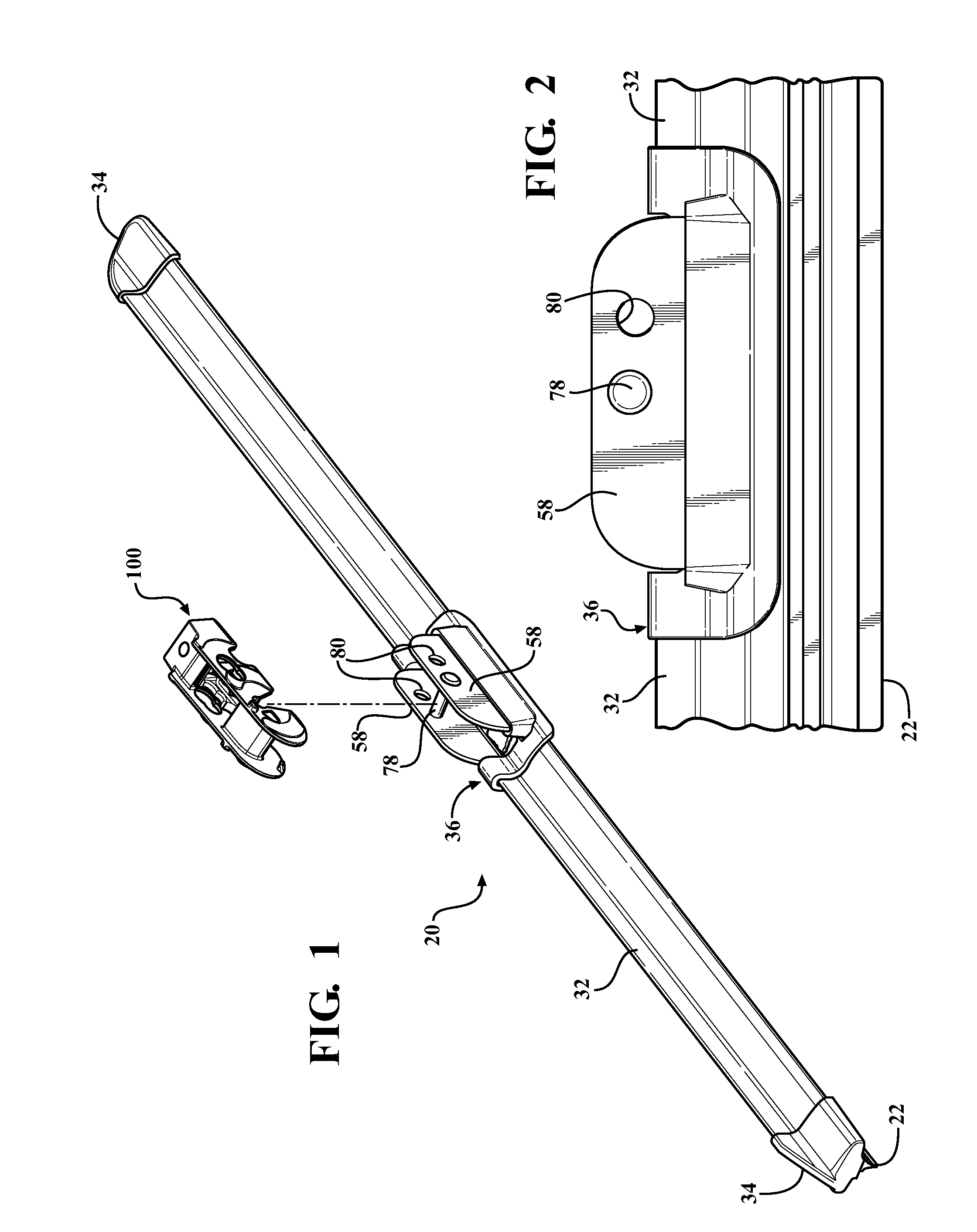
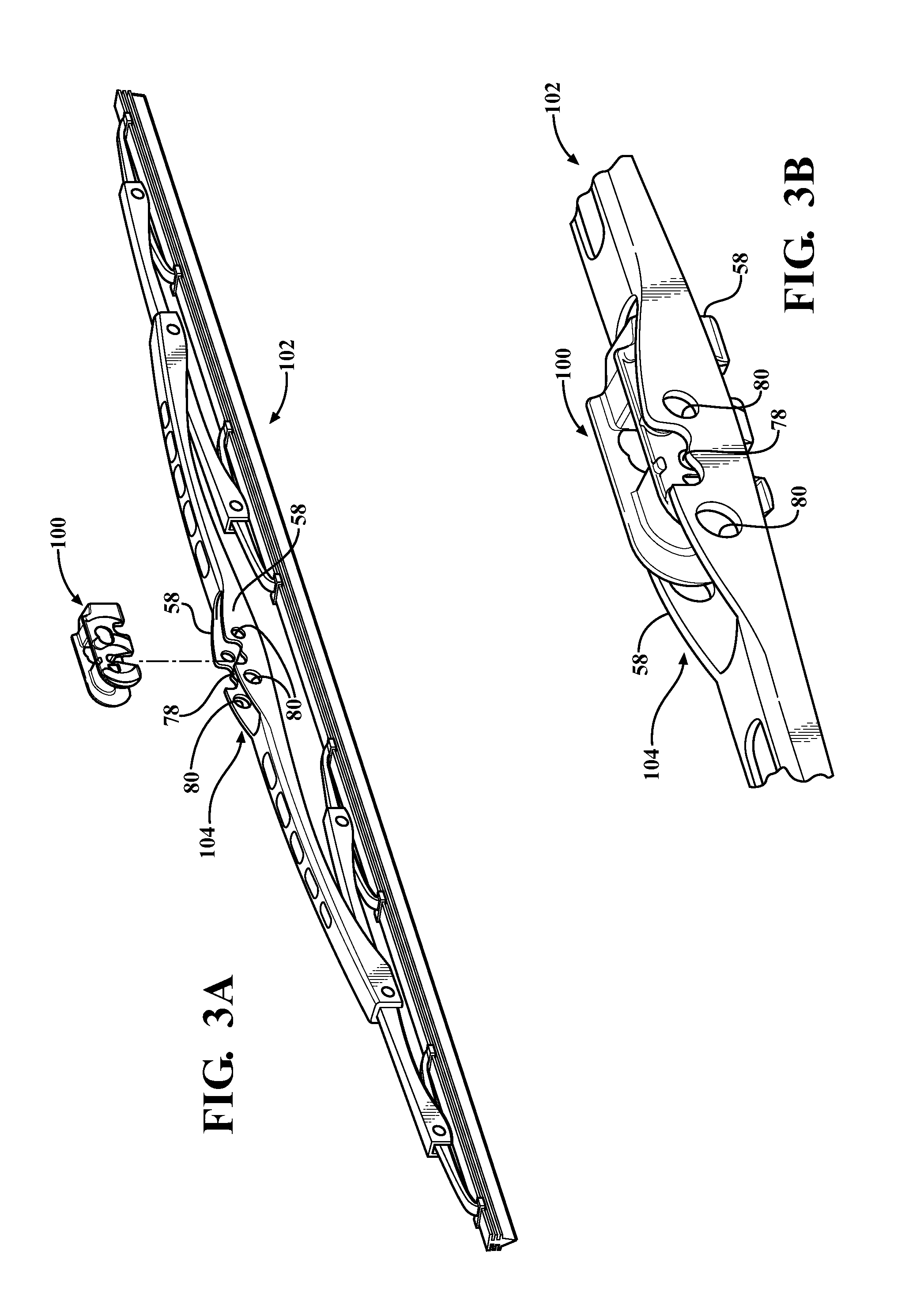
[0031]Referring to the figures, wherein like numerals indicate like or corresponding parts throughout the several views, one style of windshield wiper blade assembly is generally shown at 20 in FIGS. 1 and 2. The wiper blade assembly 20 illustrated here is of the so-called flat or yokeless type having an elongated wiper element 22 adapted for direct contact against the windshield of a motor vehicle to scrape water and snow from the windshield as the blade assembly 20 is swept back and forth in an oscillating, repetitive pattern. Spoilers 32 may be attached to the wiper blade assembly to help maintain an even pressure of the wiper element 22 against a windshield during high driving speeds. End caps 34 snap-connect in place and surround the outermost ends of each spoiler 32 to establish a finished, terminal end piece.

[0032]A bridge piece or portion 36 may be constructed in accordance with the illustrations and descriptions provided in U.S. Pat. No. 7,523,533, the entire disclosure of ...


PUM


Abstract

A universal connector (100) is adapted to connect a wiper blade assembly (20, 102) with a variety of wiper arm ends (300, 302, 304, 306, 308, 310, 312, 314, 316). In order to connect side pin type wiper arm ends (302, 304, 306), the connector includes a pin hole (216) having a figure “8” shape defined by larger and smaller overlapping lobes (218, 220). A flexible tongue (222) carried by the connector (100) includes a pair of scalloped pawls (224, 226) aligned with the respective larger and smaller lobes (218, 220) so as to engage either a ¼″ or 3 / 16″ wiper arm side pin (302-306). In order to connect wiper arm ends having hook slots (310, 312, 314 316), the connector (100) includes a generally planar upper landing (204), a generally planar lower return (206), and a forward nose profile (208). Sides (210) include cantilevered extensions (212) projecting beyond the nose profile (208) and which carry a pair of 9×4 stops (214) set below the plane of the lower return (206) by a clearance gap. When assembling a 9×3 hook end (316), the 9×4 stop (214) is bypassed entirely due to the clearance gap. However, when a 9×4 hook arm (310, 312, 314) is used, the 9×4 stops (214) retain the hook arm (310, 312, 314) in position.

Description

CROSS REFERENCE TO RELATED APPLICATIONS[0001]This application claims priority to U.S. Provisional Patent Application No. 61 / 224,591 filed Jul. 10, 2009, the entire disclosure of which is hereby incorporated by reference and relied upon.BACKGROUND OF THE INVENTION[0002]1. Field of the Invention[0003]A wiper blade assembly of the type used for clearing water from a windshield or windscreen, and more particularly toward an improved connector for joining a wiper blade to any one of various style wiper arm ends including side pin and / or hook slot styles.[0004]2. Related Art[0005]Windshield wipers are used to remove water from the windshield or windscreen of motor vehicles and in related applications. In a typical wiper assembly, a wiper blade connects to the free end of an oscillating or sweeping wiper arm through a central connection device, known as a connector. The connector is usually clipped onto the top side of the wiper blade, generally midway along its length.[0006]Traditionally,...

Claims


Application Information

Patent Timeline
Patent Type & Authority Patents(United States)
IPC IPC(8): B60S1/02
CPCB60S1/4003B60S1/4006B60S1/4074B60S1/4087B60S1/4038B60S2001/4032
Inventor KOPPEN, SCOTT ALLENBOLAND, XAVIER
Owner FEDERAL MOGUL MOTORPARTS LLC
Why Eureka
Try Eureka