

Dustproof seal for ratchet wrench
a technology of dustproof seal and ratchet wrench, which is applied in the direction of wrenches, manufacturing tools, spanners, etc., can solve the problems of unsatisfactory dustproof effect, damage to the teeth of the drive member and the bore, and insufficient torque, etc., to facilitate the description of the invention
- Summary
- Abstract
- Description
- Claims
- Application Information
AI Technical Summary
Problems solved by technology
Method used
Image

Examples
Embodiment Construction
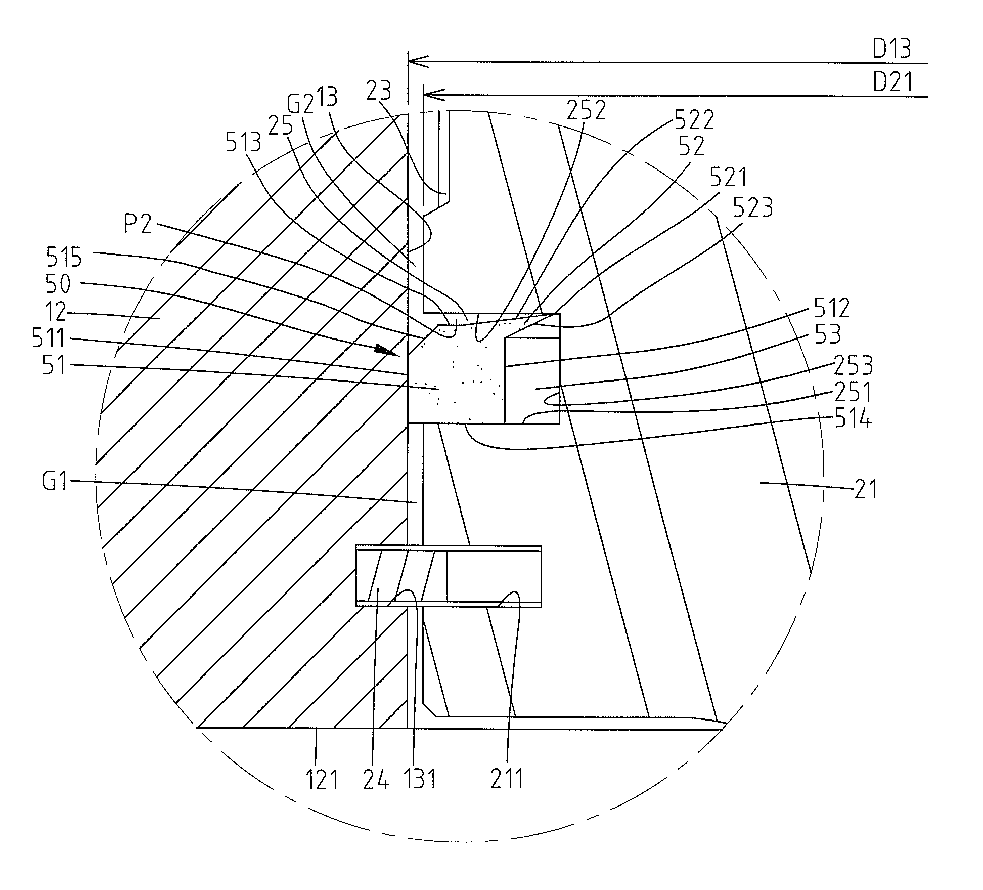
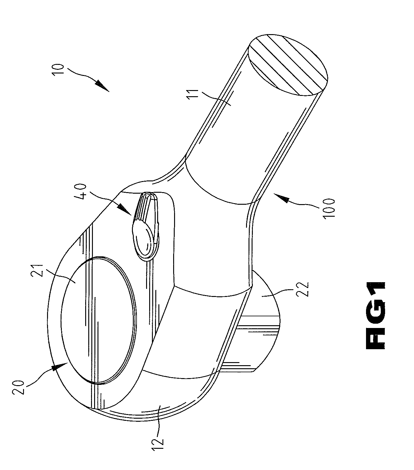
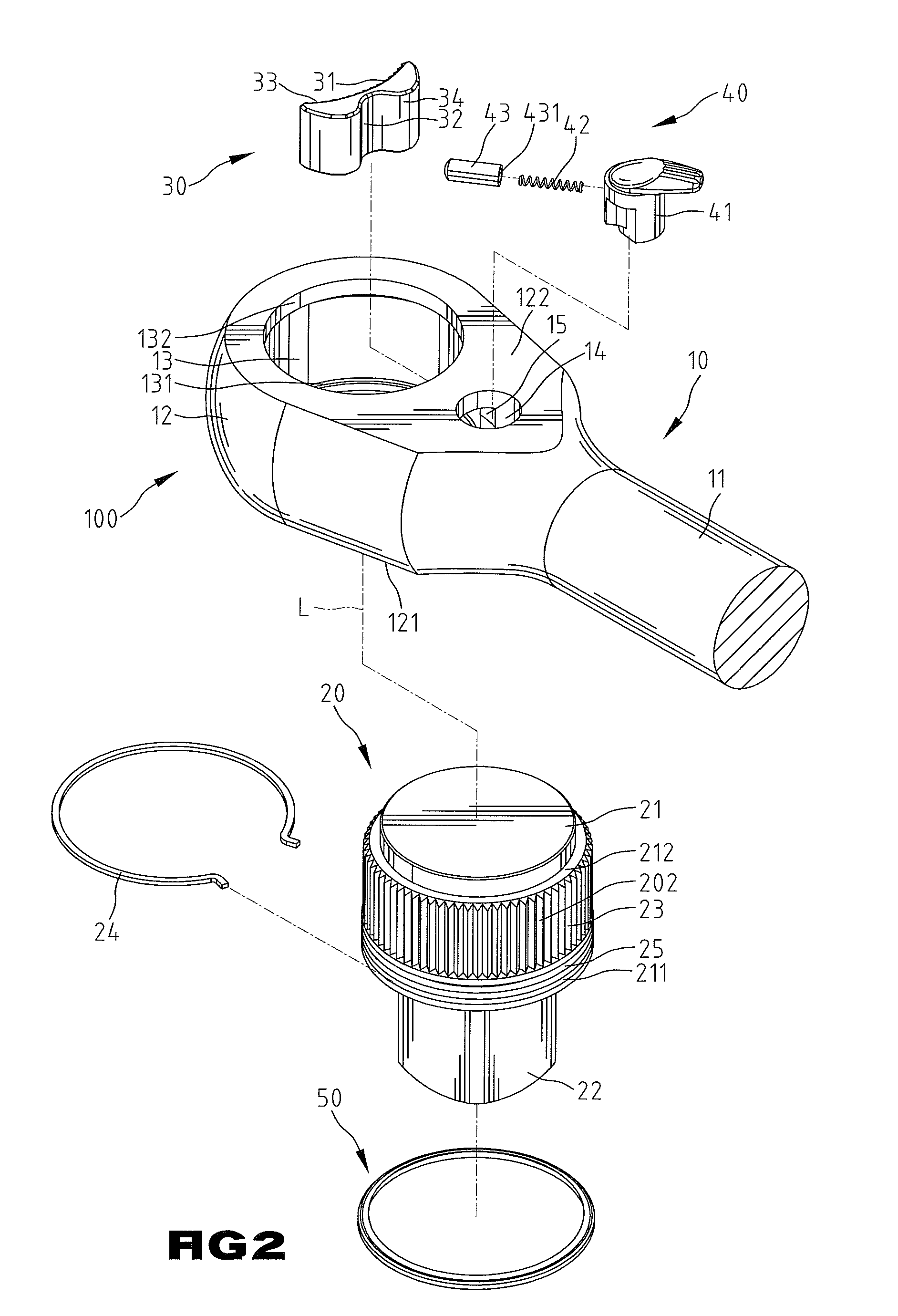
[0028]A ratchet wrench according to the preferred teachings of the present invention is shown in the drawings and generally designated 100. In preferred forms shown in FIGS. 1-16, ratchet wrench 100 includes a body 10 having a head 12 and a handle 11 interconnected to head 12. Head 12 includes first and second sides 121 and 122 spaced along an axis L. Head 12 further includes a compartment 13 extending from first side 121 through second side 122. A pawl groove 15 is defined in a peripheral wall of compartment 13. An annular flange 132 is formed on the peripheral wall of the compartment 13 at second side 122 of head 12. A switch groove 14 extends from second side 122 of head 12 toward but spaced from first side 121 of head 12 along axis L. Switch groove 14 is in communication with pawl groove 15. Pawl groove 15 is intermediate compartment 13 and switch groove 14 in a radial direction perpendicular to axis L. The peripheral wall of compartment 13 further includes an annular groove 131...
PUM
 Abstract
Description
Claims
Application Information