Sewing tool holder

a tool holder and sewing technology, applied in the field of sewing tool holders, can solve the problem of not being able to hold clips

Inactive Publication Date: 2017-04-04
CLOVER MFG CO LTD
View PDF11 Cites 3 Cited by
  • Summary
  • Abstract
  • Description
  • Claims
  • Application Information

AI Technical Summary

Problems solved by technology

The above-described needle holder can hold marking pins and the like, but cannot actually hold clips.

Method used


Image

  • Sewing tool holder
  • Sewing tool holder
  • Sewing tool holder

Examples


Embodiment Construction

[0030]Hereinafter, preferred embodiments of the present invention will be specifically described with reference to the drawings.

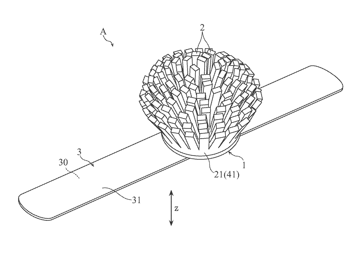
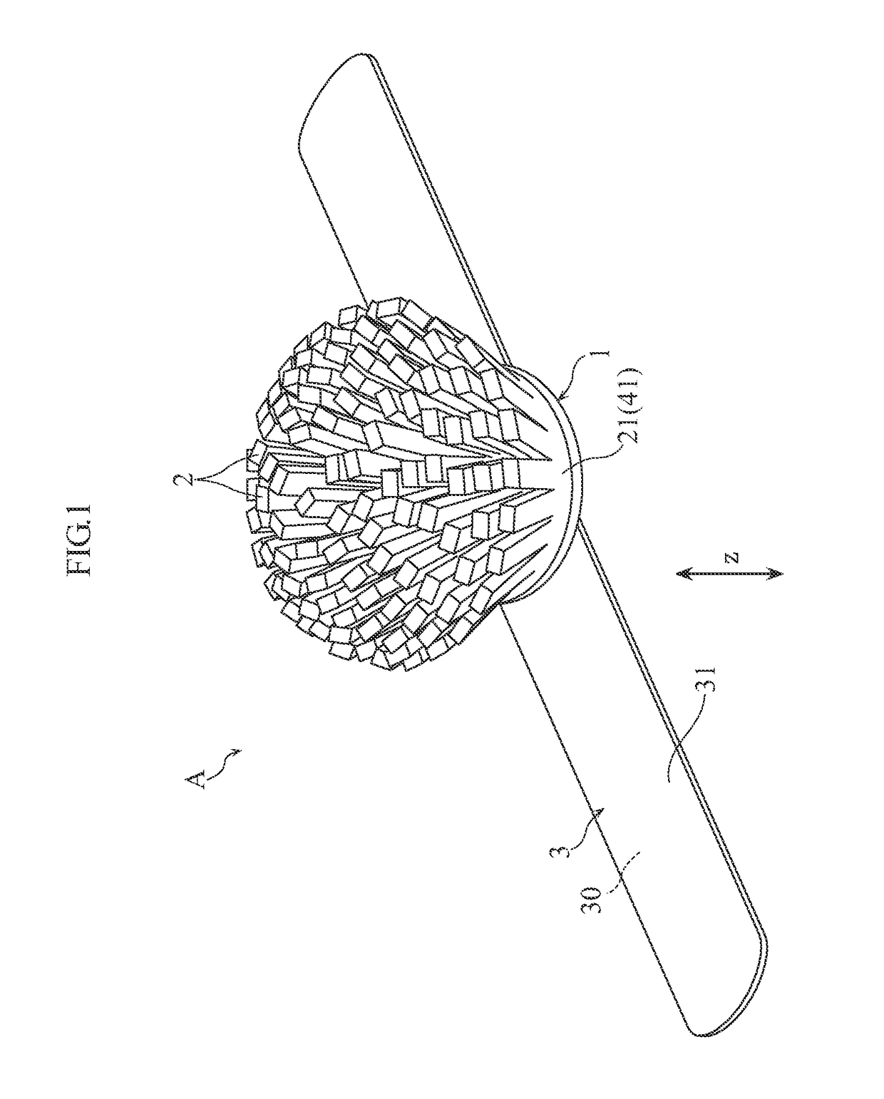
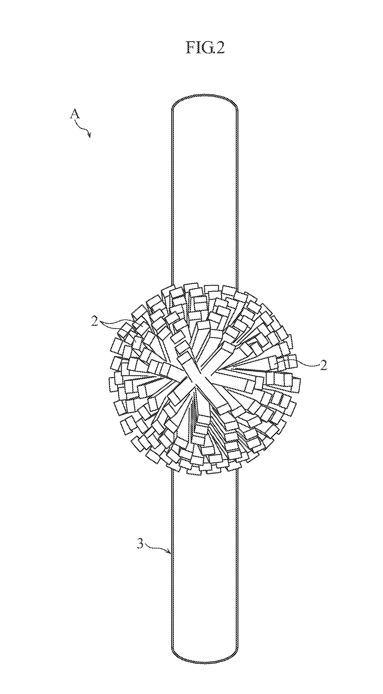
[0031]FIGS. 1 to 3 show an example of a sewing tool holder according to an embodiment the present invention. A sewing tool holder A of this embodiment includes a relatively thin base 1, a plurality of projections 2 that are supported on the base 1, and an elongated band 3 that supports the base 1. In FIG. 3, the band 3 is not illustrated.

[0032]In this embodiment, the base 1 is in the shape of a circular plate or disk, and is made of felt, for example.

[0033]The plurality of projections 2 are supported on an obverse face 10a of the base 1. In this embodiment, the plurality of projections 2 are supported on the base 1 via a common connecting portion 21, and as a whole extend in a thickness direction z of the base 1. More specifically, each projection 2 has a free front end and a fixed root end attached to the common connecting portion 21. As seen from FIG. 3, ...


PUM


Abstract

A sewing tool holder includes a base and a plurality of of projections. The base has an obverse face and a reverse face spaced from each other in a thickness direction of the base. The plurality of projections are supported on the obverse face of the base via a common connecting portion attached to the base. Each of the plurality of projections has an upper or front end and a root or lower end that is connected to the common connecting portion.

Description

BACKGROUND OF THE INVENTION[0001]1. Field of the Invention[0002]The present invention relates to a sewing tool holder for holding sewing tools such as clips and marking pins for sewing.[0003]2. Description of Related Art[0004]Typically, needles for sewing such as sewing needles and marking pins are stuck into and held in a pincushion made of a cushioning material or the like when they are not used. Furthermore, a needle holder is also proposed in which, instead of a pincushion made of a cushioning material, the magnetic force of a magnet is used to attract and hold needles for sewing and the like (see Japanese Utility Model Registration No. 3101736, for example). With such a needle holder using a magnet, metal needles for sewing can be clustered together and rigidly held.[0005]Also, a wrist-worn needle holder is known that can be worn on a user's arm (mainly the wrist portion) during a sewing operation (see Japanese Utility Model Registration No. 3043144, for example). The wrist-wor...

Claims


Application Information

Patent Timeline
Patent Type & Authority Patents(United States)
IPC IPC(8): A41H17/00A44C5/00D05B91/12
CPCD05B91/12A41H17/00A44C5/00
Inventor IWASAKI, CHIHIRO
Owner CLOVER MFG CO LTD
Why Eureka
Try Eureka