Pressure reducing valve

a technology of pressure reducing valve and sealing valve, which is applied in the direction of fluid pressure control, process and machine control, instruments, etc., can solve the problems of poor sealing performance, repeatability of sealing, and deterioration of sealing performance, so as to reduce the number of elements, improve the accuracy of sealing and sealing performance, and be easily centered

Active Publication Date: 2013-01-01
FUJIKURA COMPOSITES INC
View PDF16 Cites 10 Cited by
  • Summary
  • Abstract
  • Description
  • Claims
  • Application Information

AI Technical Summary

Benefits of technology

[0008]In view of the above described conventional pressure reducing valve, the present invention provides a pressure reducing valve which does not require lubricant even though equipped with a guide mechanism for a valve body (a main valve and a relief valve), and which makes it possible to center the valve body itself.
[0017]According to the present invention, a reduction in number of elements of the pressure reducing valve is achieved since the opening / closing valve and the relief valve can be driven by a single pintle. In addition, since the vent hole is formed on an extension of a common axis of the valve passage and the pintle hole, the valve body itself can be easily centered, and the accuracy of sealing and sealing performance are improved.

Problems solved by technology

In a diaphragm-type pressure reducing valve with no guide mechanism for the relief valve, the resistance caused upon actuation of the pressure reducing valve is small, however the relief valve becomes freely movable so that sealing repeatability is poor upon a return of the relief valve after it is opened, and accordingly, and hence the sealing performance is poor.
In addition, the sealing performance deteriorates by a positional deviation of a diaphragm assembly upon installation thereof, which is a fairly common occurring problem.
Therefore, in the case where the pressure reducing valve is used in an environment such as a clean room which does not tolerate impurities, the lubricating oil may get scattered.

Method used


Image

  • Pressure reducing valve
  • Pressure reducing valve
  • Pressure reducing valve

Examples


Embodiment Construction

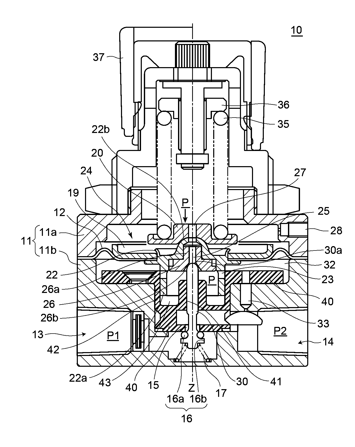
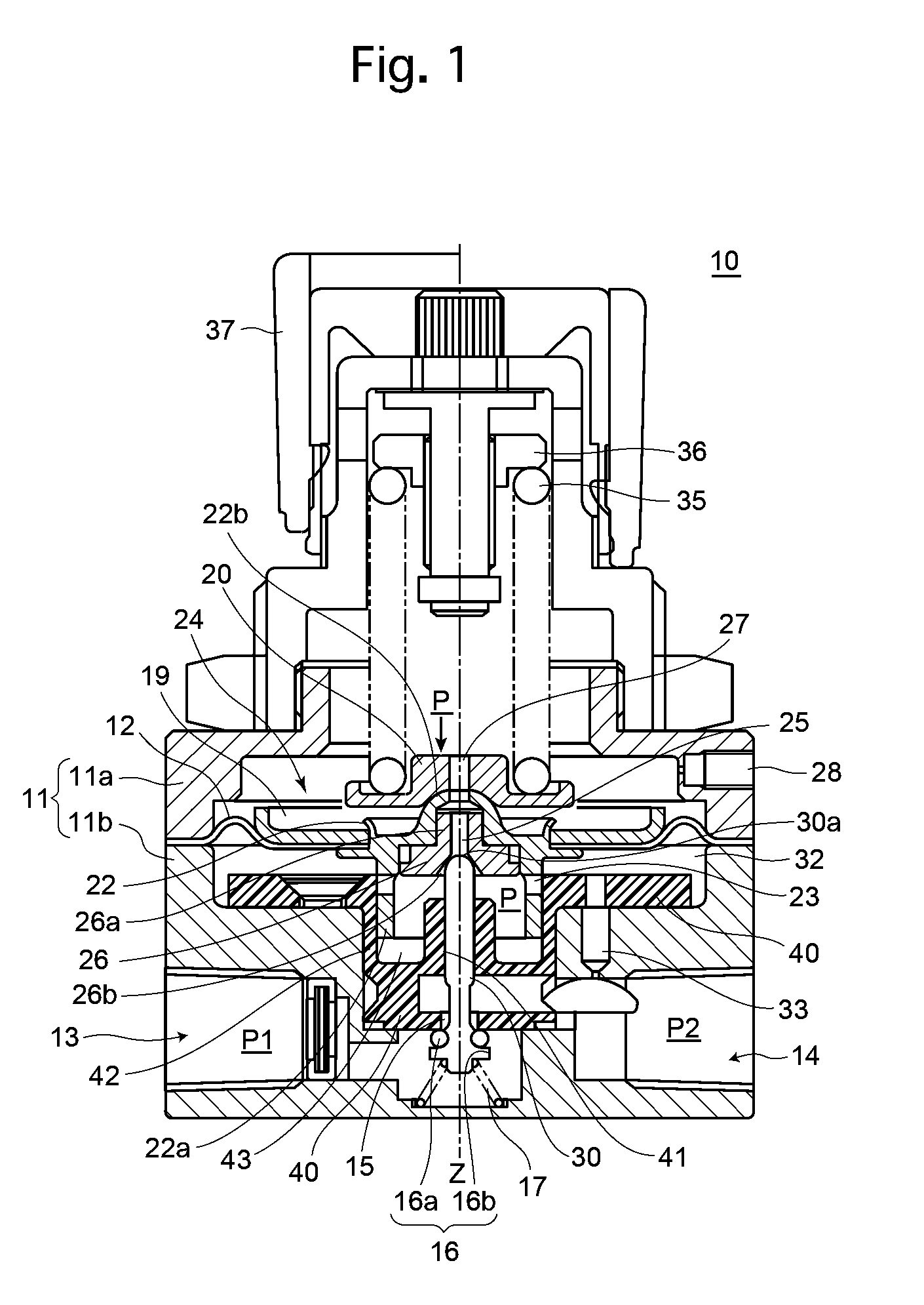
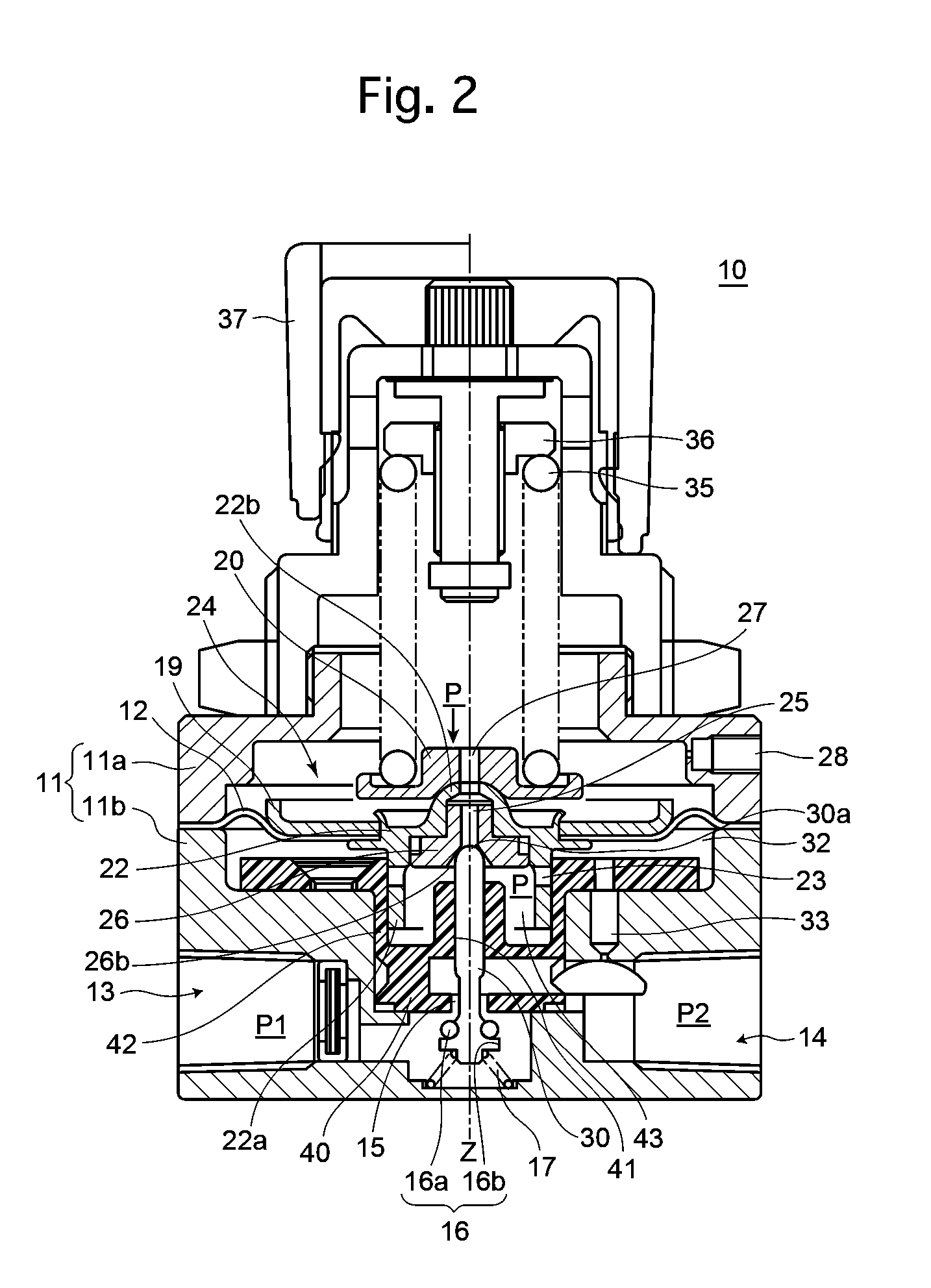
[0022]FIG. 1 is a longitudinal cross sectional view of an embodiment of a pressure reducing valve 10 according to the present invention. The pressure reducing valve 10 is provided with a housing 11 which is composed of an upper housing 11a and a lower housing 11b, and is further provided with a diaphragm 12, the outer edge of which is held between the upper and lower housings 11a and 11b.

[0023]The lower housing 11b is provided with a primary-pressure inlet port (primary pressure chamber) 13 and a secondary-pressure outlet port 14 which are open outwardly. The pressure reducing valve 10 is provided in the lower housing 11b with a valve guide 40, and the primary-pressure inlet port 13 and the secondary-pressure outlet port 14 are communicatively connected to each other through a valve passage 15 formed in the valve guide 40. The valve passage 15 is opened and closed by an opening / closing valve 16. The opening / closing valve 16 is continuously biased by a compression spring 17 in a val...


PUM


Abstract

A pressure reducing valve includes a opening / closing valve between primary and secondary pressure chambers, a diaphragm body, a valve hole through which the secondary pressure chamber is communicatively connected with the atmosphere, a relief valve which opens / closes the valve hole, and a linkage member which links the opening / closing valve with the relief valve so as to open / close in association with each other. The linkage member includes a valve guide having a valve passage through which the primary and secondary pressure chambers are communicatively connected, and a pintle inserted into a pintle hole and guided thereby. The opening / closing valve and the relief valve are provided on lower and upper ends of the pintle, respectively. The valve hole has a common axis with those of the valve passage and the pintle hole. One and the other of the valve guide and the pintle are made of resin and metal.

Description

CROSS REFERENCE TO RELATED APPLICATION[0001]The present invention is related to and claims priority of the following co-pending application, namely, Japanese Patent Application No. 2008-151769 filed on Jun. 10, 2008.BACKGROUND OF THE INVENTION[0002]1. Field of the Invention[0003]The present invention relates to a pressure reducing valve and in particular to a pressure reducing valve with a grease-free (lubricant-free) guide mechanism for guiding an opening / closing valve.[0004]2. Description of the Prior Art[0005]In conventional pressure reducing valves, a guide mechanism is often used to improve the sealing performance in a main valve and in a relief valve (air release valve) thereof. Although conventional seal-packing-type pressure reducing valves are equipped with a guide mechanism for the relief valve, the resistance imposed on movements of the relief valve due to a seal packing is great because a guiding component of the guide mechanism needs to be equipped with a sealing mechan...

Claims


Application Information

Patent Timeline
Patent Type & Authority Patents(United States)
IPC IPC(8): F16K31/12
CPCG05D16/0669Y10T137/7794Y10T137/7812
Inventor NITTA, TOSHINORI
Owner FUJIKURA COMPOSITES INC
Why Eureka
Try Eureka