Durable steam injector device

a technology of injector device and steam injection, which is applied in the direction of combustion-air/fuel-air treatment, lighting and heating apparatus, and separation processes, etc., can solve the problems of water hammer development, system disadvantages, and save a great deal of energy costs

Active Publication Date: 2013-01-01
SMITH ROBERT S
View PDF10 Cites 12 Cited by
  • Summary
  • Abstract
  • Description
  • Claims
  • Application Information

AI Technical Summary

Problems solved by technology

At high steam pressures, however, water hammer develops due to the sudden collapse of relatively large steam bubbles which are created at high pressures as it condenses within the water.
Because of this high heat-transferability, direct steam injection can save a great deal in energy costs.
However, these systems are not without their disadvantages.
Because separate lines are used for each fluid, capital equipment tends to be expensive and inconvenient to install.
In addition, changes in these variables can result in varying outlet temperatures which may not be desired.
However, as in the other prior approaches, the results have proven spotty with instability and lack of control problems being manifest.
Although applicant has previously suggested the use of static mixing elements to facilitate the injection of steam within a fluid stream, many such fluid streams, such as those effluent streams from mining operations alluded to above can cause erosion of critical elements.
Although static mixing elements, by their very definition, have no moving parts and are thus relatively inexpensive to install and service, when servicing is required, the cost and inconvenience of doing so can be significant as processing lines must be shut down or diverted and various pipelines disconnected in order to gain access to their interiors.

Method used


Image

  • Durable steam injector device
  • Durable steam injector device

Examples


Embodiment Construction

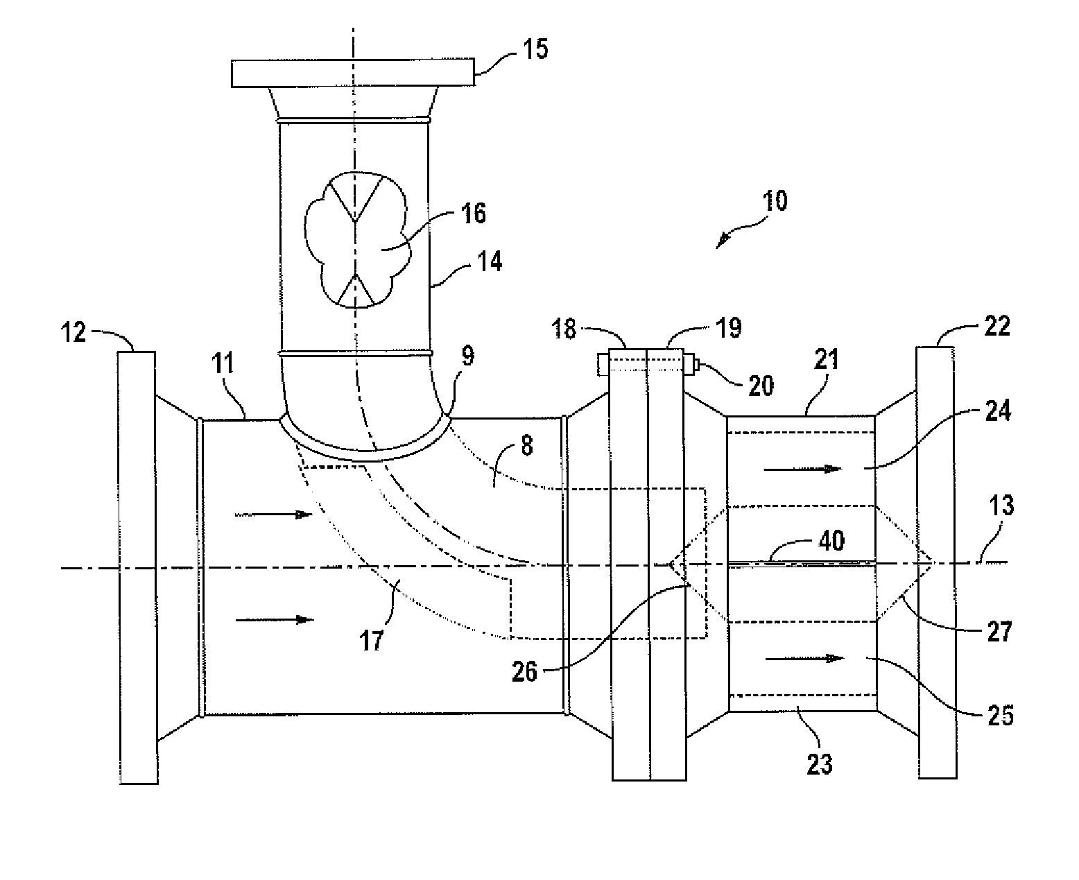
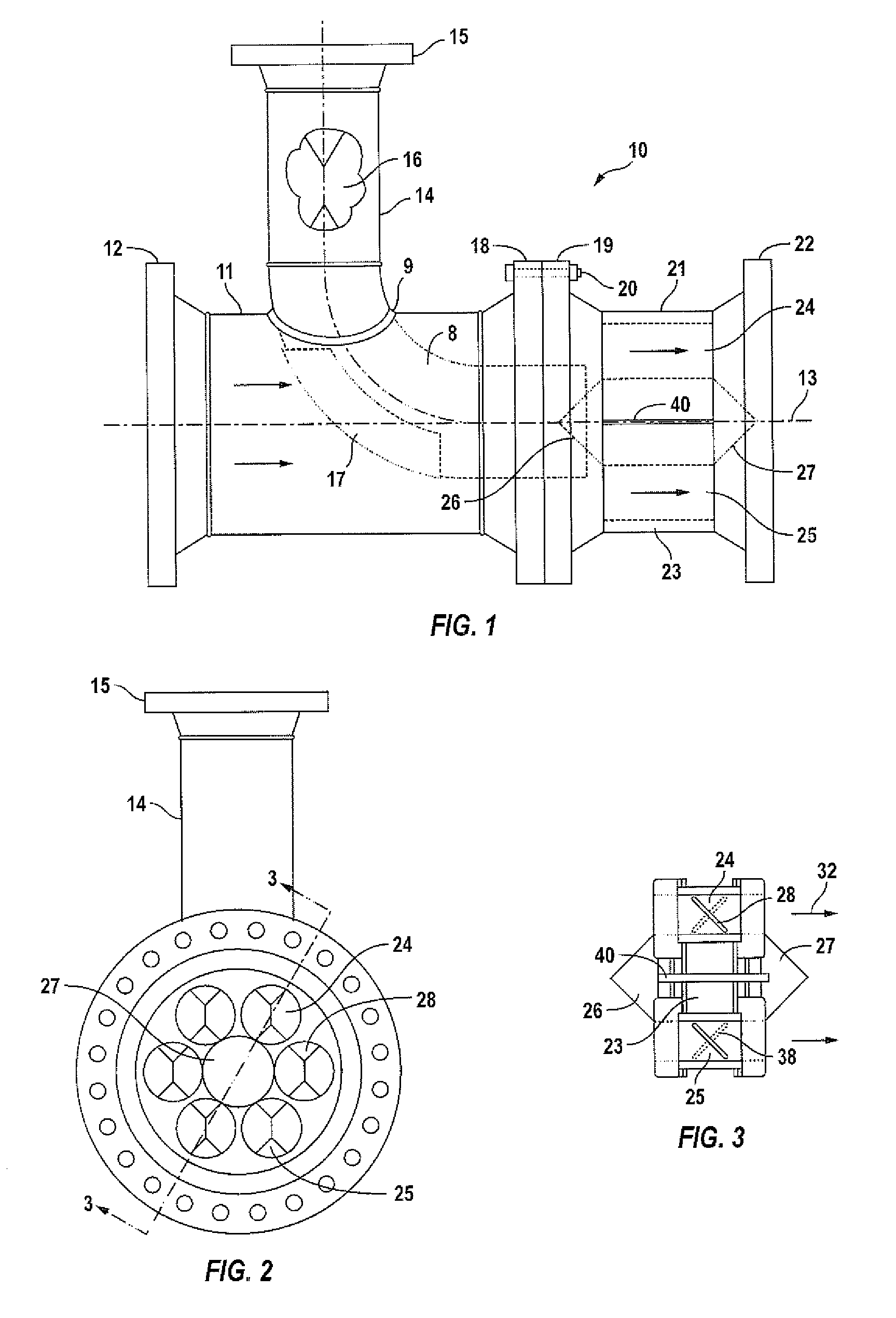
[0018]Novel features which are characteristic of the invention, as to organization and method of operation, together with further objects and advantages thereof will be better understood from the following description considered in connection with the accompanying drawings, in which preferred embodiments in the invention are illustrated by way of example. It is to be expressly understood, however, that the drawings are for the illustration description only and are not intended as definitions of the limits of the invention. The various features of novelty which characterize the invention are recited with particularity in the claims.

[0019]There has been broadly outlined more important features of the invention in the summary above and in order that the detailed description which follows may be better understood, and in order that the present contribution to the art may be appreciated. There are, of course, additional features of the invention that will be described hereinafter and whi...


PUM

PropertyMeasurementUnit
pressuresaaaaaaaaaa
diameteraaaaaaaaaa
pressuresaaaaaaaaaa

Abstract

A device for the injection and mixing of steam into a fluid stream. The device is intended to be used in a substantially cylindrically-shaped primary conduit having a longitudinal axis and circular cross-section for carrying the fluid stream. The primary conduit is provided with an inlet for accepting the fluid stream and an outlet for discharging the fluid stream along the longitudinal axis. A secondary conduit is joined to the primary conduit for discharging steam within the fluid stream along the longitudinal axis. A biscuit element is provided of sintered tungsten having upstream and downstream circular faces sized to fit within the primary conduit along its interior wall having a geometric center coincident with the longitudinal axis and having a plurality of openings, each having a longitudinal axis parallel to the longitudinal axis of the primary conduit. Each opening is provided with a mixing element that induces a rotational angular velocity to the fluid stream passing therethrough. Conically-shaped features extend from the circular faces and are centered along the longitudinal axis at the geometric centers thereof.

Description

TECHNICAL FIELD[0001]The present invention is directed to a highly efficient steam injector, a steam injection heater for the heating of liquids moving within a conduit. For example, waste effluent from mining operations including mining tailings are processed in order to remove solvent from its aqueous carrier liquid. Separation of this effluent stream into its component parts is facilitated by heating. An excellent way to do so is through the use of a steam injector device such as that of the present invention.BACKGROUND OF THE INVENTION[0002]Steam injection has been a unit operation carried out by chemical engineers in processing facilities for as long as chemical engineering has been a science. For example, a typical steam injection water heater was disclosed in U.S. Pat. No. 2,455,498. Subsequently, U.S. Pat. No. 3,984,504 dealt with the fabrication of a rather complex device used to eliminate water hammer which has characterized steam injection systems in the past. It was reco...

Claims


Application Information

Patent Timeline
Patent Type & Authority Patents(United States)
IPC IPC(8): B01F3/04
CPCB01F5/0618B01F13/1022F28C3/06B01F25/4316B01F33/813B01F23/23767
Inventor SMITH, ROBERT S
Owner SMITH ROBERT S
Why Eureka
Try Eureka