
Curved assembly for reattachment of fragmented bone segments

a fragmented bone and screw technology, applied in the field of orthopedic bone screws and drills used in the reattachment of fragmented bone segments, can solve the problems of nullifying the tendency of spiral threads to compress and bind on the shaft, and achieve the effect of preventing unraveling of threads and improving the mechanical performance of devices

Inactive Publication Date: 2013-01-01
TOBY ORTHOPAEDICS
View PDF19 Cites 42 Cited by
  • Summary
  • Abstract
  • Description
  • Claims
  • Application Information

AI Technical Summary

Benefits of technology

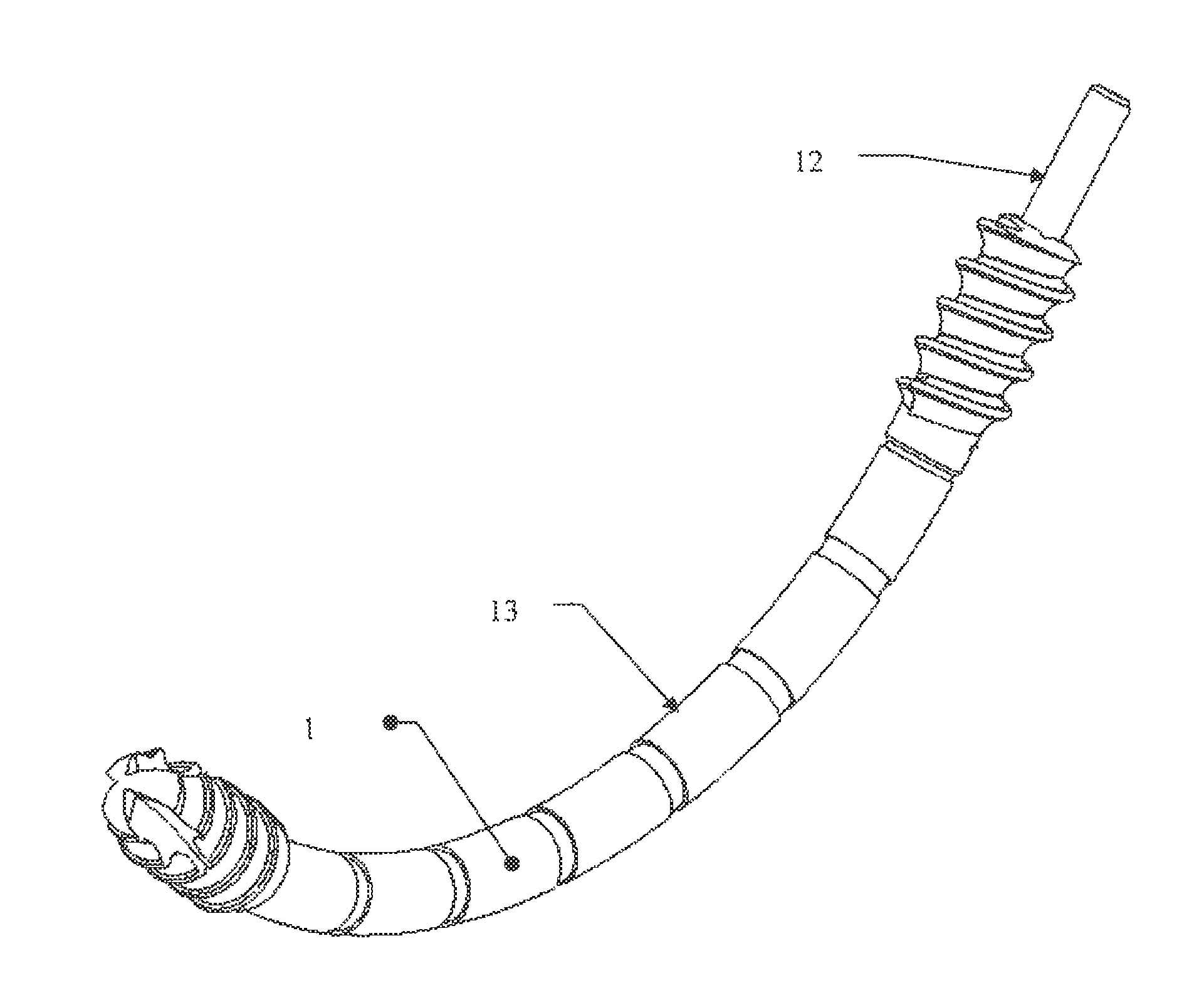
[0015]In another embodiment of the present invention, the flexible sleeve with screw tip and screw head is externally threaded. The threaded sleeve is preferably made of a spiral thread that articulates with multiple rings, preferably at regular intervals on the thread to prevent unraveling of the thread when the screw tip and screw head are advanced. The rings that hold the spiral thread to the rigid curved shaft, while free to rotate, can be kept from sliding along the curved shaft by features along the shaft such as snap rings or other prominences. In a preferred embodiment, a freely rotating ring alternates with a snap-ring. In this manner, the transfer of the driving thrust of the spiral thread is more uniform at every snap ring or prominence holding the rings of the thread, and not only at the head of the screw. Thus holding the rings that stabilize the thread in the same position along the curved assembly improves the mechanical performance of the device and approximates the articulated curved screw as much as possible to a straight screw. In addition, when the screw is backed out, the tendency of the spiral thread to compress and bind on the shaft is nullified by the rings that stabilize the thread to the shaft. In this embodiment, the screw could be removed in a delayed fashion without concern for bone building up along the shaft in between the head and the tip of the screw.
[0016]In yet another embodiment of the present invention, the curved assembly comprises a hollow rigid sleeve encasing a hollow or solid flexible drive shaft, wherein said flexible drive shaft connects the head of the screw with the tip of the screw. The curved assembly has another component comprised of a flexible sleeve which is externally threaded. The flexible sleeve would also connect the head of the screw with the tip of the screw. In this embodiment, the head of the screw is driven via the flexible shaft and not the outer flexible threaded sleeve. Torque transfer from the head of the screw to the tip of the screw takes place through the flexible drive shaft minimizing the tendency of the threaded sleeve to unravel.

Problems solved by technology

In addition, when the screw is backed out, the tendency of the spiral thread to compress and bind on the shaft is nullified by the rings that stabilize the thread to the shaft.

Method used


Image

  • Curved assembly for reattachment of fragmented bone segments
  • Curved assembly for reattachment of fragmented bone segments
  • Curved assembly for reattachment of fragmented bone segments

Examples


Embodiment Construction

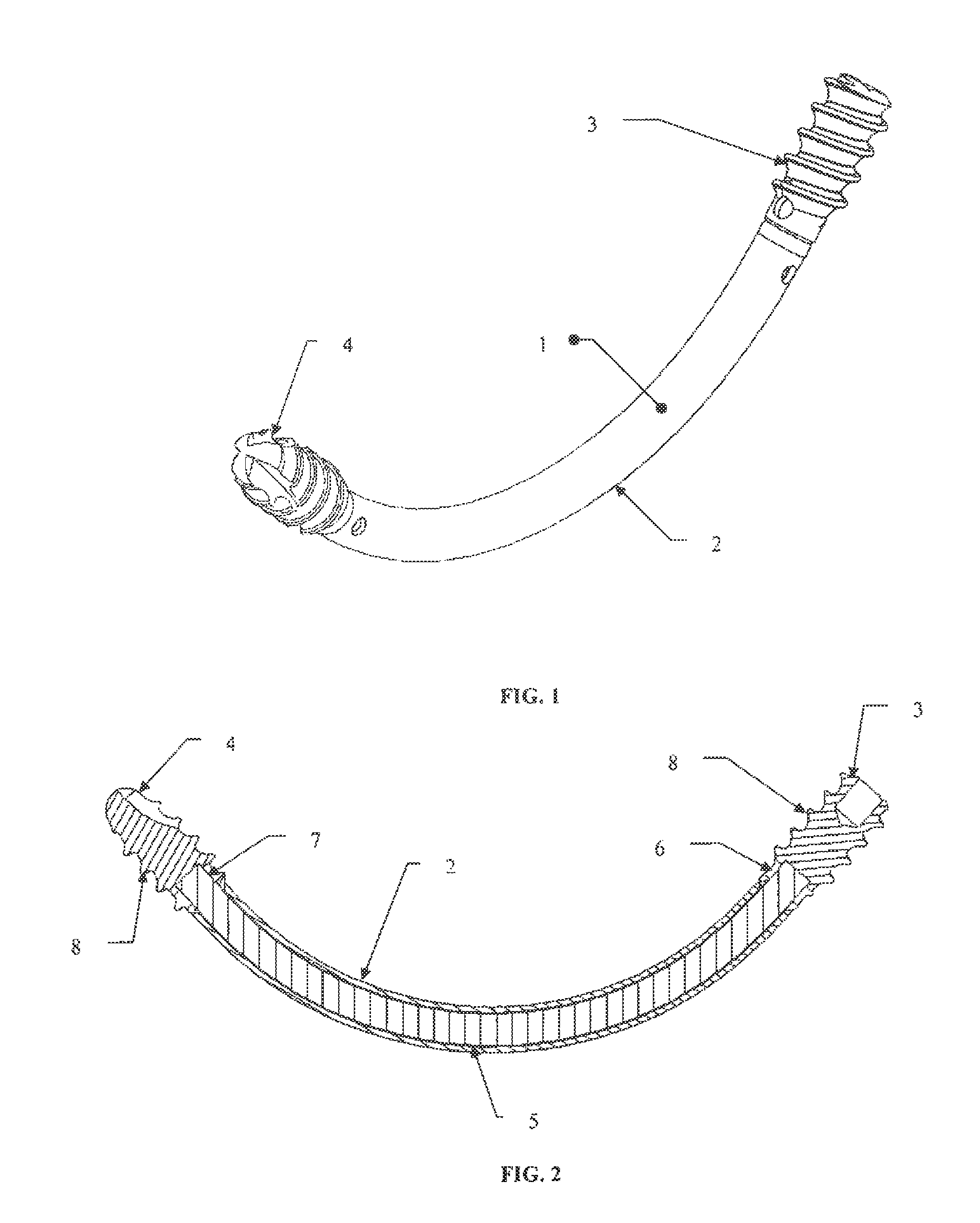
[0028]FIG. 1, depicts a curved assembly 1 comprised of a curved sleeve 2 with a proximally attached screw head 3 and a distally attached screw tip 4. In one embodiment of the present invention, the curved sleeve 1 is rigid, and can be made of any implantable material used by those of ordinary skill in the art, including but not limited to titanium alloys or stainless steels. In this embodiment, the rigid sleeve determines the curvature of the curved assembly.

[0029]The inner portion of curved sleeve is hollow and shaped to encase an inner member. As illustrated by FIG. 2, inner member is comprised of a drive shaft 5. The drive shaft 5 comprises a first proximal end 6 attached to a screw head 3 and a second distal end 7 attached to a screw tip 4. In one embodiment of the present invention, the drive shaft 5 is flexible, can be hollow or solid, and can be made of any implantable material used by those of ordinary skill in the art.

[0030]As illustrated by FIG. 2, the flexible drive shaft...


PUM


Abstract

The present invention is comprised generally of a curved assembly for use in reattaching bone segments created by fracture or for mating bone fragments in other reconstructive procedures. The present invention further comprises a curved drill to create the hole into which the curved screw is attached. Preferably, the curved screw and drill of the present invention are designed such that they can be used singularly or in combination with a bone plate to support bone fragments and prevent them from moving with respect to the plate.

Description

CROSS REFERENCES TO RELATED APPLICATIONS[0001]This application claims the benefit under 35 U.S.C. §119(e) of U.S. Provisional Application No. 60 / 922,651, filed on Apr. 11, 2007, the complete disclosure of which is incorporated herein by reference in its entirety.FIELD OF THE INVENTION[0002]The present invention relates to orthopedic bone screws and drills used in the reattachment of fragmented bone segments.BACKGROUND OF THE INVENTION[0003]The present device and method provides a significant departure from straight screws for fixation of bone or other solid material.[0004]Traditional screws are basically solid devices with a head that articulates with a screwdriver, a straight shaft, and a tip. The shaft may be fully threaded or only partially threaded; a portion of the tip may be threaded and may or may not have a self drilling or self tapping design. In addition, the head of the screw itself may have threads that articulate with a metal plate to assist the screw in locking to the ...

Claims


Application Information

Patent Timeline
Patent Type & Authority Patents(United States)
IPC IPC(8): A61B17/80
CPCA61B17/1728A61B17/8866A61B2019/481A61B2090/08021
Inventor GONZALEZ-HERNANDEZ, EDUARDO
Owner TOBY ORTHOPAEDICS
Learn More