Methods for configuring sender and receiver antennas, corresponding storage means and nodes

a technology for sending and receiving antennas, applied in the field of communication systems, can solve the problems of increasing the sensitivity of the antenna in reception, limiting the radio range of such systems to about ten meters, and reducing the sensitivity of the antenna in the reception field

Active Publication Date: 2013-01-01
CANON KK
View PDF19 Cites 30 Cited by
  • Summary
  • Abstract
  • Description
  • Claims
  • Application Information

AI Technical Summary

Benefits of technology

[0045]The general principle of this embodiment of the invention therefore consists in taking advantage of data transmission in a first mode (for example a redundancy of transmissions) in a wireless mesh communications network to determine an optimum angle of antenna aim (or more generally possible parameters of antenna configuration) of a first node (sender of point-to-point transmission) and a second node (receiver of the point-to-point transmission) making it possible to ensure sufficient quality of data transmission in a second mode (point-to-point mode) between these nodes.
[0047]Since such an initiation of configuration is done during transmission in the first mode (for example with transmission redundancy), a reconfiguration of point-to-point transmission can be done without having to use the bandwidth reserved for transmitting data in the point-to-point mode and therefore makes it possible to maintain data transmission according to the point-to-point mode from the first node to the second node at each transmission cycle despite changes in conditions of propagation between these nodes.
[0074]Thus, should a readjustment of the antenna parameters (in other words an antenna reconfiguration) for a point-to-point transmission be unnecessary (because no particular disturbance appears to be present in the common coverage area of the receiver and sender antennas), the invention provides for using the working of the transmission redundancy mode (with relaying by network meshing) so that the nodes concerned carry out their data relaying function during the time slot normally planned for this purpose and thus reinforce the robustness of the communications between the nodes of the network.
[0115]second means for determining said receiving configuration by selecting a configuration corresponding to an angle of antenna orientation, from among said plurality of angles, for which the associated level of quality of reception is the best.

Problems solved by technology

Besides, the radio range of such systems is limited to about ten meters, favoring the re-utilization of the frequencies in time and space.
Moreover, in this carrier frequency band, the attenuation of the radio signal in air is great.
The use of this type of antenna at reception of a radio signal increases the sensitivity of the antenna in reception in a desired direction and reduces the sensitivity of this antenna in areas of interference or highly noisy areas.
The search for an optimum angle of antenna orientation is a recurrent technical problem in antenna communications networks configured directionally.
Indeed, owing to the short wavelengths used (millimeter waves) such communications systems are highly sensitive to phenomena of interference and shadowing.
The drawback of such a method lies in the fact that it cannot be implemented during a communications link-up.
Indeed, such a method requires the receiver nodes of the network to orient their receiver antenna and scrutinize in directions other than the one needed for receiving payload data sent out by a sender node considered, thus giving rise to a loss of payload data during this period of time.
However, because of a bandwidth that is generally limited for such home networks, the redundancy of transmissions applied in these mesh communications networks prove to be ill-adapted to applications calling for a data stream at a higher bit rate (of the order of about 100 Mbps) such as video applications for example.
This type of relay in fact does not have any means of communication with the other devices of the network because it does not have any sender or receiver antennas.
One of the main difficulties encountered when implementing a WPAN type home communications network based on a TDMA protocol and on directionally configured antennas is that of being able to swiftly and reliably determine the antenna orientation angles of a sender node and a receiver node so as to ensure constantly high quality communications of data in point-to-point transmission between these nodes.
The optimum aiming of an antenna in a given direction is generally difficult to maintain over time owing to the short radio wavelengths used in these wireless communications systems.
Indeed, the smallest shift by the nodes of the network or a variation in the aiming precision due for example to a drift in temperature or an ageing of certain electronic components may affect the quality of a radio communications link-up.
This technical problem is particularly worrisome in the case of certain communications, especially involving data streams at high bit rates, which allow neither transmission redundancy nor a use of the bandwidth to carry out optimal aiming of the antennas of each node.
One drawback of this prior art technique is that it makes it necessary to set up an additional communications path, namely a communications path other than the one used to transmit applications data, to obtain an adequate adjustment of the antenna orientation angles.
Such a method therefore generates additional costs and complexity of implementation.
Another drawback of such a technique is that it cannot be used to ensure lossless transmission of application data, because the antenna adjustments cannot be done before each operation for sending application data, which is especially true in the specific case of transmission of data at high bit rates in a communications network supporting a highly fluctuating radio communications channel.

Method used


Image

  • Methods for configuring sender and receiver antennas, corresponding storage means and nodes
  • Methods for configuring sender and receiver antennas, corresponding storage means and nodes
  • Methods for configuring sender and receiver antennas, corresponding storage means and nodes

Examples


Embodiment Construction

[0145]In all the figures of the present document, the identical elements and steps are designated by a same numerical reference.

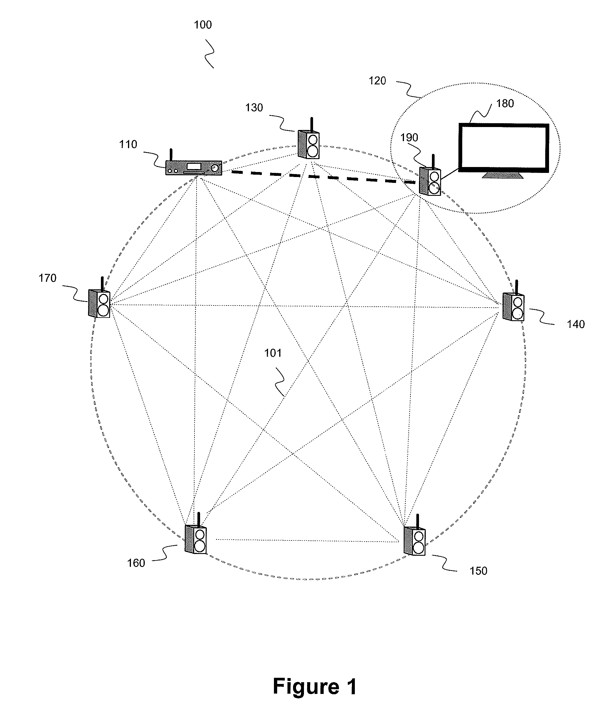
[0146]FIG. 1 is an example of a wireless communications network 100 in which the methods for configuring according to a particular embodiment compliant with the invention can be implemented.

[0147]More particularly, the network 100 of FIG. 1 illustrates a wireless (5.1 home cinema type) video and audio distribution network using millimeter waves about the 60 GHz frequency band. The network 100 comprises a source device 110 and a plurality of sender and receiver nodes 120, 130, 140, 150, 160 and 170, each node being capable of behaving alternately as a sender node and as a receiver node and having only one antenna for the transmission and reception of radio data signals. Furthermore, certain nodes may play the role of relay nodes, i.e. they retransmit on the network data that they have preliminarily received from another node. The nodes of the network 100 are...


PUM


Abstract

Methods for configuring antennas of first and second nodes of a wireless communications network clocked by transmission cycles, each cycle being divided into time slots, the first node and second nodes having first and second time slots for transmitting data in the first mode, the first node having a third time slot for transmitting data to the second node in a second mode, are proposed. The configuring method, on the second node side, comprises steps of determining a receiving configuration of the antenna of the second node, verifying that the determined receiving configuration is invariant, relative to a receiving configuration previously used for receiving data transmitted from the first node to the second node in the second mode; in the event of negative verification: sending a predetermined signal in the second mode, by using a sending configuration that is determined based on the determined receiving configuration; configuring, during the third time slot, the antenna of the second node by using this determined receiving configuration.

Description

1. FIELD OF THE INVENTION[0001]The field of the invention is that of communications systems and more particularly wireless communications systems using millimeter radiowave sender and receiver antennas such as for example wireless home networks or WPANs (wireless personal area networks) using the 60 GHz bandwidth.[0002]More specifically, the invention concerns a technique for configuring sender and receiver antennas in a wireless communications network implementing a synchronous time division multiplexing (TDM) type of transmission.2. TECHNOLOGICAL BACKGROUND2.1 Context of the Invention[0003]Wireless home audio and video applications are now increasingly numerous and require ever higher data bit rates of the order of some Gigabits per second (here below denoted as Gbps) and an increasingly higher quality of service. WPAN millimeter type home networks are particularly well suited to this type of application. Indeed, the authorized band about a carrier frequency of 60 GHz offers a wid...

Claims


Application Information

Patent Timeline
Patent Type & Authority Patents(United States)
IPC IPC(8): H04L12/28
CPCH04B7/0617H04B7/088H04B7/0695
Inventor THOUMY, FRANCOISCAILLERIE, ALAIN
Owner CANON KK
Why Eureka
Try Eureka