Securing mechanism cooperating with a device that is to be secured

a technology of a locking mechanism and a locking position, which is applied in the direction of permutation locks, nuts, bolts, etc., can solve the problem of almost impossible identification of locking positions, and achieve poor manufacturing tolerances

Inactive Publication Date: 2013-01-08
BSS BAUMANN SICHERHEITSSYST
View PDF25 Cites 2 Cited by
  • Summary
  • Abstract
  • Description
  • Claims
  • Application Information

AI Technical Summary

Benefits of technology

[0004]It is the object of the present invention to improve the prior-art securing mechanism in such a way that it is no longer possible to sense the locking positions of the locking elements even with forceful tilting and poor manufacturing tolerances.

Problems solved by technology

Moreover, the prior-art advantages of this solution continue to exist and exist in addition, which means that a far-reaching protection against mechanical damage is achieved and, since all locking elements must be moved into certain positions to lock them, identifying the locking positions is nearly impossible, especially if a large number of locking elements exists.

Method used


Image

  • Securing mechanism cooperating with a device that is to be secured
  • Securing mechanism cooperating with a device that is to be secured
  • Securing mechanism cooperating with a device that is to be secured

Examples


Embodiment Construction

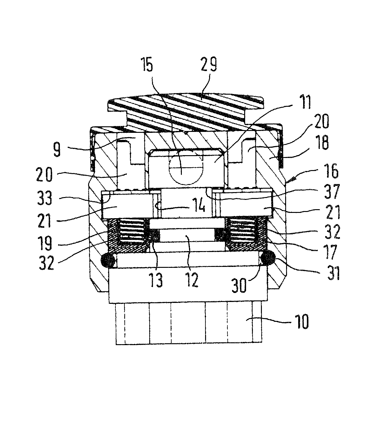
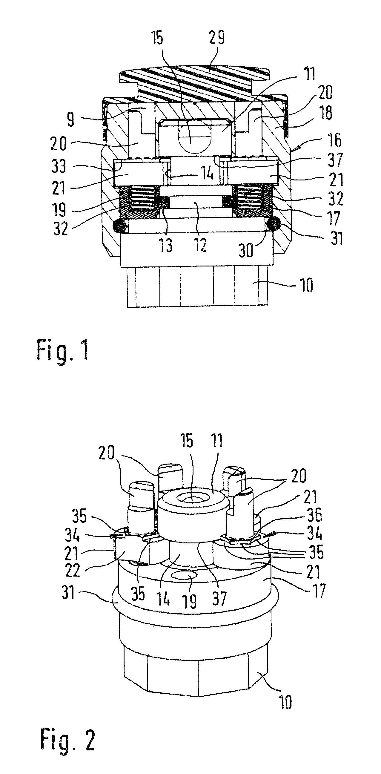
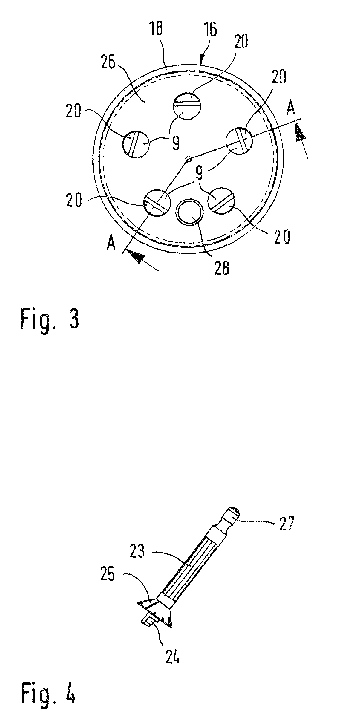
[0026]In the first exemplary embodiment shown in FIGS. 1 through 3, a device 10 that is to be secured is a rod-like or cylinder-like part, of which only an end region is shown. It may be a bolt, a nut, a bicycle axle, part of a shackle-type connector, or the like. At the end being secured of this device, an integral cylindrical extension 11 is provided concentrically, for example molded on in one piece, which has a smaller diameter and a smaller annular groove 12 for accommodating an annular seal 13 that also serves as a brake during the rotation and during a pulling movement, and a larger annular groove 14 that serves as an annular locking groove and whose function will be explained in more detail further below. This cylindrical extension 11 has a hardened steel ball 15 concentrically pressed-in at its end, which serves to prevent the assembly from being drilled open.

[0027]In the case of an embodiment in the form of a bolt, the cylindrical extension 11 is designed as a point of app...


PUM


Abstract

A securing mechanism cooperating with a device that is to be secured, having a closing part, which can be slipped onto a free end region of the device. Locking elements are rotatably mounted in the closing part and engage into an annular groove of the device by an engaging element to lock it, except in one defined position of rotation. An adjusting member engages in an end region of the locking elements accessible from outside. A spring presses the locking element against a contact area of the closing part in the direction of the axis of rotation thereof forming a brake. A catching structure provided with a plurality of catching points is disposed on an annular surface of the locking elements. A catching element engages into the catching points when the respective locking element is rotated, at least when the closing part is tilted.

Description

FIELD OF THE INVENTION[0001]The invention relates to a securing mechanism cooperating with a device that is to be secured, having a closing part, which can be plugged into a bore of the device that is to be secured, or slipped onto a free end region of the device that is to be secured, and in which at least two locking elements are rotatably mounted and engage into an annular groove of the device that is to be secured by means of an engaging element in order to lock the same except in one defined position of rotation, wherein an end region of the locking elements that is accessible from outside is implemented in each case so as to allow an adjusting member to engage therein.BACKGROUND OF THE INVENTION[0002]In a securing mechanism of this type that is known from EP 0360125 B1, the device that is to be secured is implemented in the form of a bolt, especially as a lug bolt for motor vehicle wheels. In the secured state the locking element is rotatably mounted on the free end region of ...

Claims


Application Information

Patent Timeline
Patent Type & Authority Patents(United States)
IPC IPC(8): B65D55/14F16B41/00
CPCE05B37/12F16B41/005E05B67/36Y10T70/5571Y10T70/5589Y10T70/5606Y10T70/5854Y10T70/5867Y10T70/7277Y10T70/7282Y10T70/739
Inventor SCHMIDT, REINHOLD
Owner BSS BAUMANN SICHERHEITSSYST
Why Eureka
Try Eureka