Aerosol Generation Device With Closure

Pending Publication Date: 2022-05-12
JT INT SA
View PDF0 Cites 0 Cited by
  • Summary
  • Abstract
  • Description
  • Claims
  • Application Information

AI Technical Summary

Benefits of technology

The described arrangement allows the closure to be opened and closed by a resilient element, which also helps to improve the feel of the closure and counteract any undesired movement. This results from the resilient member's tendency to force the closure towards or away from the user's hand as they interact with it.

Problems solved by technology

Furthermore, the aerosol and vapour produced by heating the aerosol substrate, e.g. tobacco, does not typically comprise the burnt or bitter taste resulting from combustion and burning that can be unpleasant for the user.
Existing aerosol generation devices can be awkward to use and the required components can lack user-friendliness.
For example, it is helpful to provide a cover that can protect the region of the device where the aerosol substrate is provided for use; this cover is moved frequently by the user of the device and so a cover that lacks user-friendliness is undesirable.
In both of the prior art publications, the lid is simple and no mechanism for effectively controlling movement of the lid is disclosed.

Method used


Image

  • Aerosol Generation Device With Closure
  • Aerosol Generation Device With Closure
  • Aerosol Generation Device With Closure

Examples


first embodiment

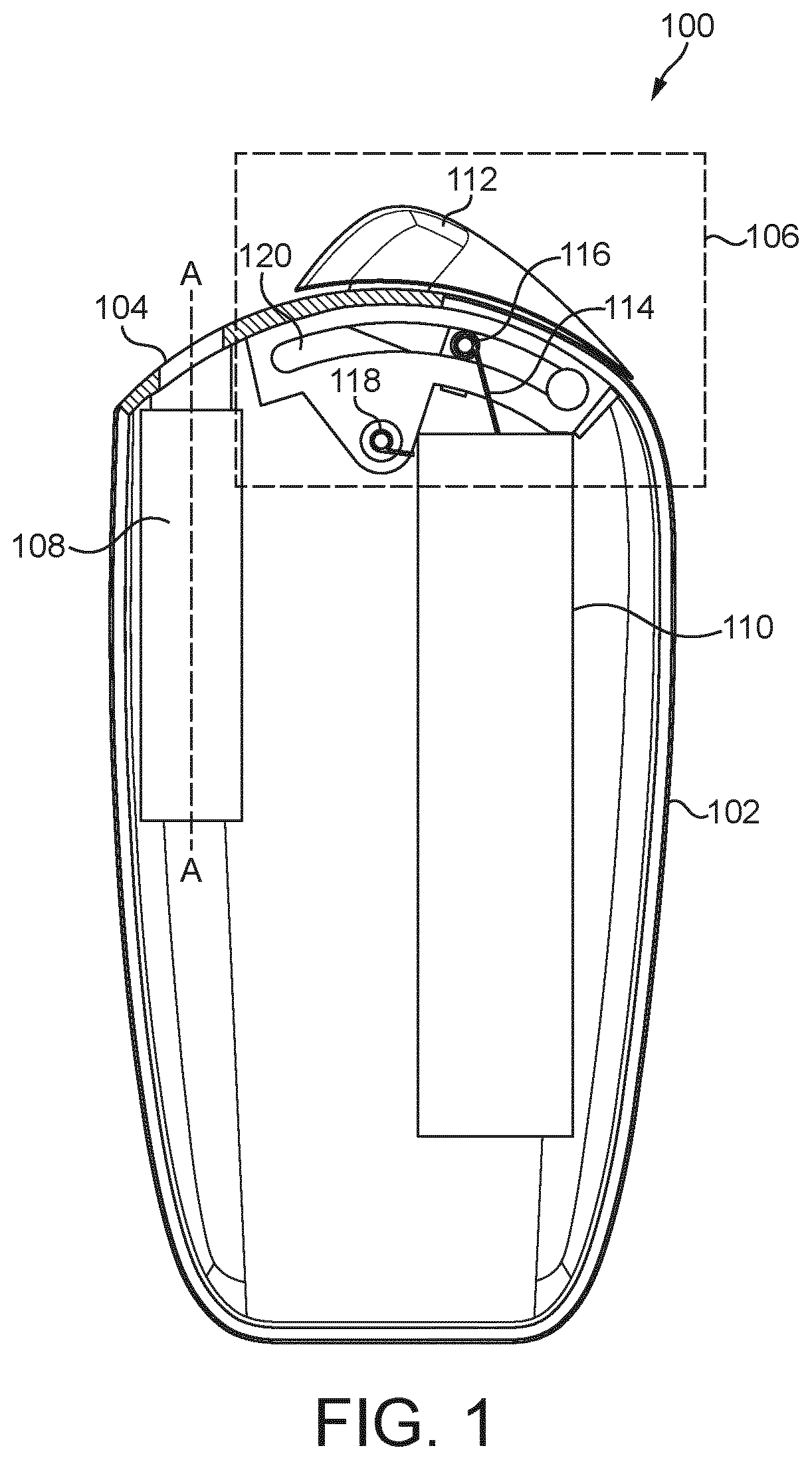
[0112]Referring to FIG. 1, according to a first embodiment of the disclosure, an aerosol generation device 100 comprises a body 102 housing various components of the aerosol generation device 100. The body 102 can be any shape so long as it is sized to fit the components described in the aerosol generation device 100. The body 102 can be formed of any suitable material, or indeed layers of material.

[0113]A first end of the aerosol generation device 100 that is an end near to the closure 106, shown towards the top of FIG. 1, is described for convenience as the top or upper end of the aerosol generation device 100. A second end of the aerosol generation device 100 that is an end further from the closure 106, shown towards the bottom of FIG. 1, is described for convenience as a bottom, base or lower end of the aerosol generation device 100. Movement from the top of the aerosol generation device 100 to the bottom of the aerosol generation device 100 is described for convenience as down,...

second embodiment

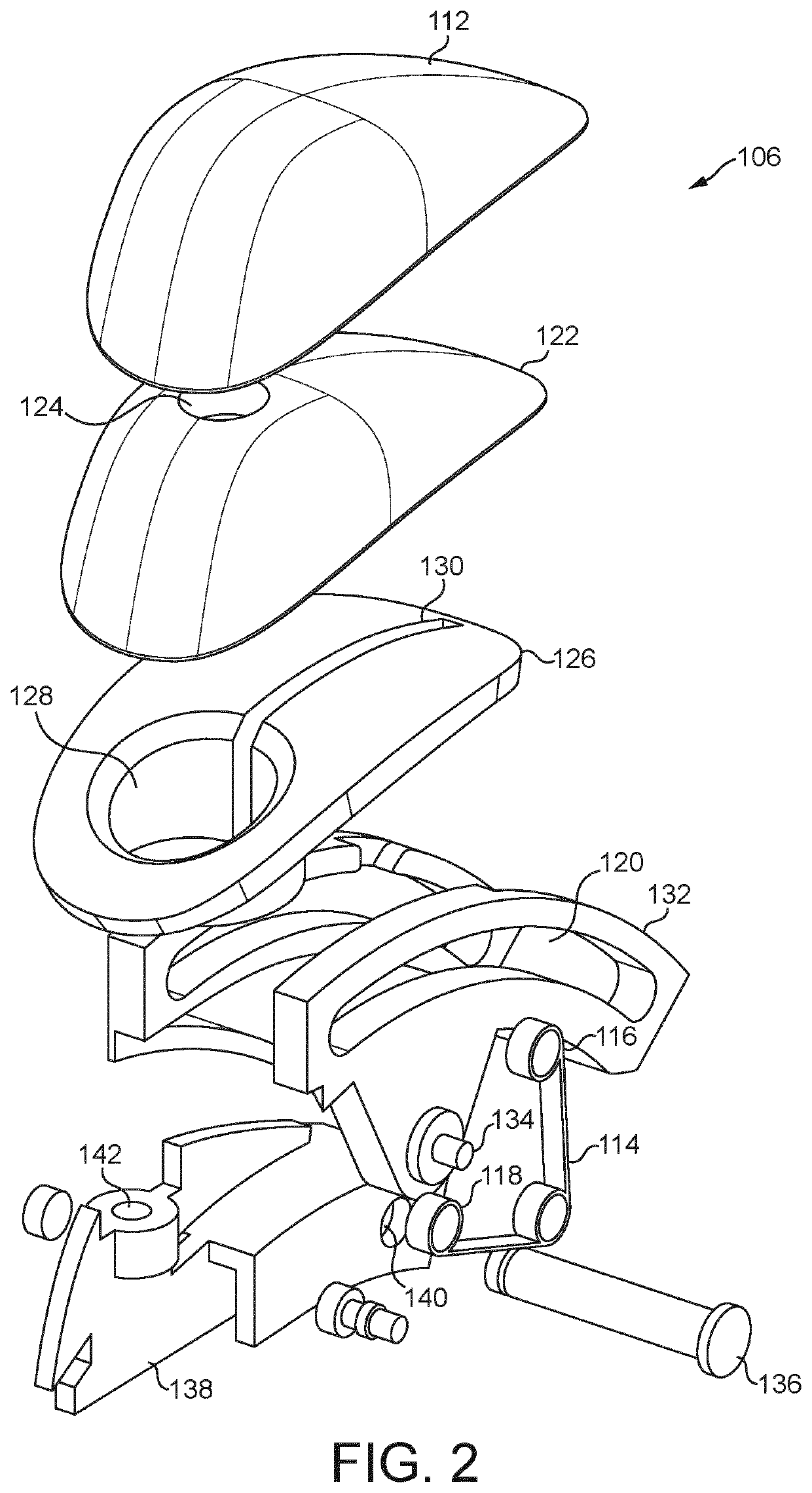
[0181]Referring to FIG. 6, an aerosol generation device 100 according to a second embodiment of the closure 106 is identical to the aerosol generation device 100 of the first embodiment, described with reference to FIGS. 1 to 5, except that the linkage 138 of the second embodiment differs from that of the first embodiment. In the second embodiment, the linkage 138 comprises a main body section, a prong 162 that extends from one side of the body of the linkage 138 and a guard attachment 142 that extends from the other side of the body of the linkage 138. The linkage 138 is sized so that the body of the linkage 138 and the prong 162 of the linkage 138 are able to pass through the channel 130 of the aperture cover 126.

[0182]The linkage 138 further comprises: a first pin 150, a second pin 154 and a third pin 158; and a first pin hole 152, second pin hole 156, and a third pin hole 160. The first pin 150 is arranged to fit into the first pin hole 152, the second pin 154 is arranged to fit...

third embodiment

[0190]Referring to FIG. 8, an aerosol generation device 100 according to a third embodiment of the closure 106 is identical to the aerosol generation device 100 of the second embodiment, described with reference to FIGS. 6 to 7, except that the linkage 138 comprises a guard attachment 142 arranged to be attached, via the channel 130, near the end of the guard 122 that is furthest from the aperture 104. Typically, the guard attachment 142 of the third embodiment also runs along a substantial portion of the guard 122 to ensure a firm connection.

[0191]The guard attachment 122 is arranged to pass through the channel 130 so that it can be attached to the guard 122, which is external to the body 102 of the aerosol generation device 100. As the guard attachment 122 is arranged to be attached to the end of the guard 122 furthest from the aperture 104, when the closure 106 is in the closed position, the guard attachment 142 is offset from the aperture 104, while the external cover 112 extend...


PUM


Abstract

An aerosol generation device has a body, a closure, and a resilient element. The body has an aperture through which an aerosol substrate is receivable. The closure is moveable relative to the aperture between a closed position in which the closure covers the aperture and an open position in which the aperture is substantially unobstructed by the closure. The resilient element is arranged so as to bias the closure towards the closed position from a first range of positions between the closed position and the open position and to bias the closure towards the open position from a second range of positions between the closed position and the open position. The first range of positions of the closure is closer to the closed position than the second range of positions. The second range of positions of the closure is closer to the open position than the first range of positions.

Description

FIELD OF THE DISCLOSURE[0001]The present disclosure relates to an aerosol generation device having a closure. The closure may be arranged so as to be moveable between a closed position and an open position. The disclosure is particularly, but not exclusively, applicable to a portable aerosol generation device, which may be self-contained and low temperature. Such devices may heat, rather than burn, tobacco or other suitable materials by conduction, convection, and / or radiation, to generate an aerosol for inhalation.BACKGROUND TO THE DISCLOSURE[0002]The popularity and use of reduced-risk or modified-risk devices (also known as vaporisers) has grown rapidly in the past few years as an aid to assist habitual smokers wishing to quit smoking traditional tobacco products such as cigarettes, cigars, cigarillos, and rolling tobacco. Various devices and systems are available that heat or agitate an aerosol substrate to produce an aerosol and / or vapour for inhalation, as opposed to burning to...

Claims


Application Information

Patent Timeline
IPC IPC(8): A24F40/40A24F40/20A24F40/51
CPCA24F40/40A24F40/51A24F40/20A24F40/60A24D1/20
Inventor MASON, JONLYELL, NATHANPLEVNIK, MARKO
Owner JT INT SA
Why Eureka
Try Eureka