
Two-stage electromechanically controlled braking system for a multiaxle road vehicles

a multi-axle road vehicle, electromechanical control technology, applied in brake action initiation, brake system, railway braking system, etc., can solve the problems of slow response time of pneumatic control braking system, and inability to fully control the braking system. to achieve the effect of guarantying the comfort and safety of passengers

Inactive Publication Date: 2013-01-08
LOHR IND
View PDF16 Cites 0 Cited by
  • Summary
  • Abstract
  • Description
  • Claims
  • Application Information

AI Technical Summary

Benefits of technology

[0008]One of the present invention's objectives is to provide a braking system suitable for public transport vehicles, which ensures progressive and moderate braking that guarantees the comfort and safety of passengers. Such a progressive system can perfectly well be envisaged in this type of application, the more so since public transport vehicles generally circulate in reserved lanes, i.e. with no circulation constraints in relation to other vehicles. The driver therefore knows exactly where and when his vehicle has to stop, and can accordingly anticipate the operations of deceleration and braking.
[0009]A further disadvantage of the classical, pneumatically controlled braking system is its slow response time. In effect, in a long vehicle and in particular a public transport train with several carriages and thus several axles, the propagation of the pneumatic control along the whole vehicle takes a certain amount of time.
[0010]Whereas the brake elements on the first axles come into action a short time after a braking command has been given by the driver, those at the other end of the vehicle are actuated after a fairly substantial delay. Such a situation reduces the efficacy of the resultant braking, produces uneven wear of the brake mechanisms, and induces unsatisfactory dynamic behavior of the vehicle.
[0011]A further objective of the invention is to provide a braking system that is perfectly effective, has a much shorter response time, and produces less and also better-distributed wear of the brake mechanisms. Thanks to such a system the dynamic behavior of the vehicle is optimized in order to ensure the greatest possible comfort and safety of the passengers.
[0014]Pneumatically controlled pneumatic braking is perfectly reliable and safe. The braking system according to the invention still uses that type of braking for the emergency braking, while overcoming its disadvantages. It also enables the response time to be reduced and ensures complete efficacy of the resultant braking.
[0015]Thus, for multi-axle road vehicles there is need for a pneumatic braking system which enables both progressive and moderate service braking, and reliable and effective emergency braking, while ensuring the comfort and safety of passengers.

Problems solved by technology

A further disadvantage of the classical, pneumatically controlled braking system is its slow response time.
In effect, in a long vehicle and in particular a public transport train with several carriages and thus several axles, the propagation of the pneumatic control along the whole vehicle takes a certain amount of time.
Whereas the brake elements on the first axles come into action a short time after a braking command has been given by the driver, those at the other end of the vehicle are actuated after a fairly substantial delay.
Such a situation reduces the efficacy of the resultant braking, produces uneven wear of the brake mechanisms, and induces unsatisfactory dynamic behavior of the vehicle.

Method used


Image

  • Two-stage electromechanically controlled braking system for a multiaxle road vehicles
  • Two-stage electromechanically controlled braking system for a multiaxle road vehicles
  • Two-stage electromechanically controlled braking system for a multiaxle road vehicles

Examples


Embodiment Construction

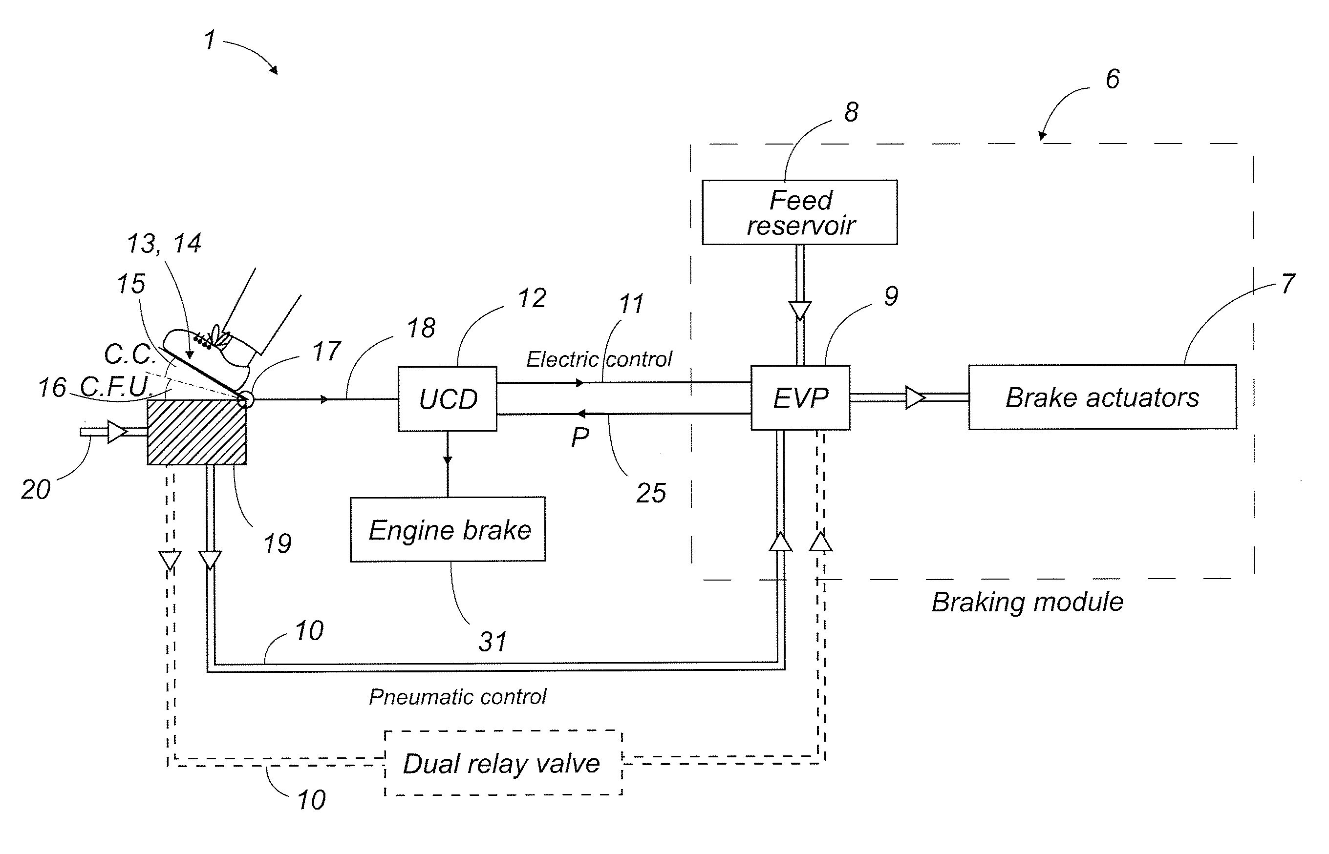
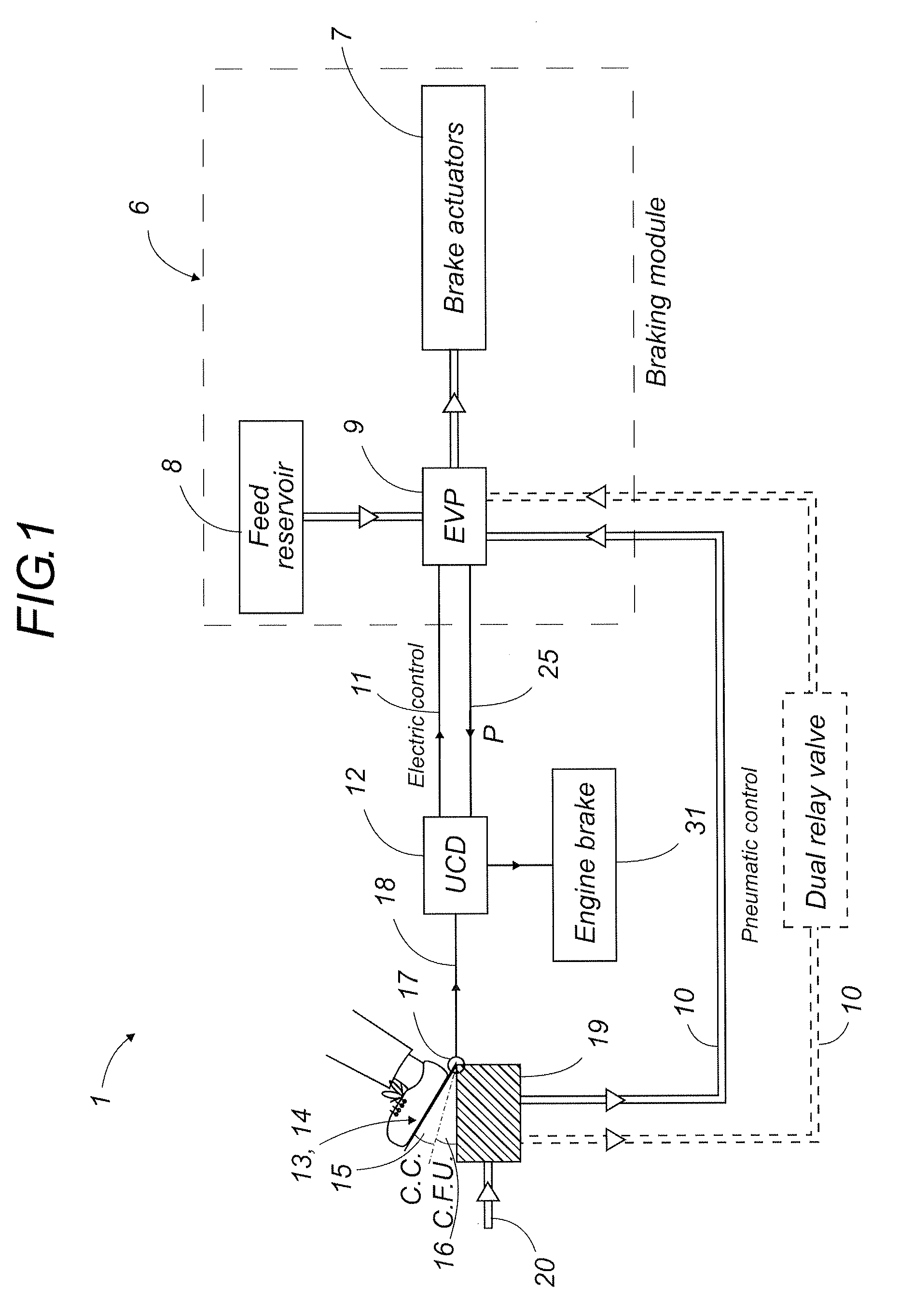
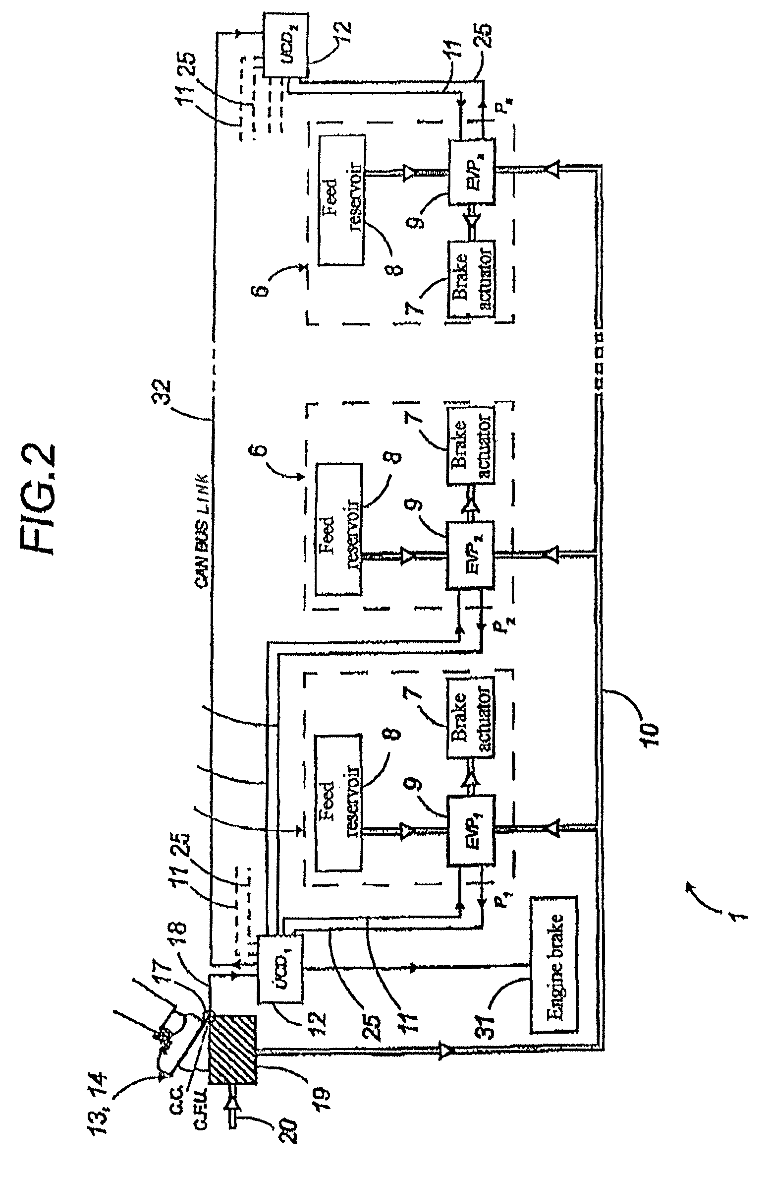
[0033]The braking system according to the present invention will now be described in detail, with reference to FIGS. 1 to 8. Equivalent elements shown in the various figures are given the same index numbers.

[0034]The present invention relates to an electromechanically controlled braking system for a multi-axle articulated road vehicle, in particular for carrying passengers. Clearly, that application is only an example and many other applications in multi-axle ground vehicles are possible.

[0035]Referring to FIGS. 3 and 4, the braking system 1 according to the invention is designed more particularly for installation on a preferably multi-axial road train 2 for public transport. This train 2 consists of a plurality of road modules articulated to one another, with at least one head module 3, and one or more carriages 4 intended for passenger transport and carried by intermediate modules such as 5, each having an axle.

[0036]Classically, the train 2 preferably has a head module 3 at each ...


PUM


Abstract

A brake system (1) having a number of sub-assemblies including a foot brake pedal (14) whose two stages correspond to service and emergency modes. Pneumatic brake modules (6) are assigned to each axle and have a proportional solenoid valve EVP (9). At least one deceleration controlling UCD unit (12) receives information from the pedal related to the pedal's position and electrically controls the brake motor (31) and / or the EVP in the service and emergency modes. A pneumatic control circuit, which is actuated in the emergency mode, controls the EVP directly from the pneumatic box (19) of the pedal. The brake system (1) is suitable for articulated multi-axle road vehicles and used, in particular, for passenger transport.

Description

[0001]This is a national stage completion of PCT / FR2006 / 002649 filed Dec. 5, 2006 which claims priority from French Application Serial No. 0512372 filed Dec. 6, 2005.FIELD OF THE INVENTION[0002]The present invention relates to a two-stage, electromechanically controlled braking system for a multi-axle road vehicle, in particular used in the context of public transport.[0003]A particular application concerns a multi-axle train on tires for public transport, comprising a self-steering unit.BACKGROUND OF THE INVENTION[0004]Road vehicles for passenger transport are generally provided with a very powerful braking system that enables them to be stopped quickly. This braking system is classically a pneumatically controlled pneumatic braking system. Such a system, available on the market, is perfectly reliable and safe.[0005]However, under normal conditions of use, if the driver actuates such a system somewhat abruptly, the public transport vehicle also stops abruptly and this can be very u...

Claims


Application Information

Patent Timeline
Patent Type & Authority Patents(United States)
IPC IPC(8): B60T7/00
CPCB60T15/048B60T13/683B60T15/04B60T13/00B60T7/04B61H11/00
Inventor AUDREZET, ARNAUDANDRE, JEAN-LUC
Owner LOHR IND
Learn More