Extremity imaging apparatus for cone beam computed tomography

a computed tomography and extremity imaging technology, applied in the field of diagnostic imaging, can solve the problems of difficult to obtain cbct, hampered cbct imaging of legs, arms, other extremities, etc., and achieve the effect of achieving a much more than about 180 degree revolution for knee or other imaging

Active Publication Date: 2013-01-08
CARESTREAM HEALTH INC
View PDF14 Cites 32 Cited by
  • Summary
  • Abstract
  • Description
  • Claims
  • Application Information

AI Technical Summary

Benefits of technology

[0016]It is an advantage of the present invention that it allows imaging of load-bearing extremities for a patient who is standing.
[0017]From one aspect, the present invention provides apparatus for cone beam computed tomography of an extremity of a patient, the apparatus comprising: a digital radiation detector; a first device to move the detector along at least a portion of a circular detector path, the portion of the detector path extending so that the detector moves both at least partially around a first extremity of the patient and between the first extremity and a second, adjacent extremity of the patient, the detector path having a radius R1 that is sufficiently long to allow the first extremity of the patient to be positioned approximately at a center of the detector path; a radiation source; a second device to move the source along at least a portion of a concentric circular source path having a radius R2 greater than radius R1, radius R2 being sufficiently long to allow adequate radiation exposure of the first extremity for an image capture by the detector; and a first circumferential gap in the source path to allow the second extremity to be positioned in the first circumferential gap during the image capture.
[0018]According to another aspect, the present invention provides an apparatus for cone beam computed tomography of a portion of a subject leg of a patient who is standing on the subject leg and its paired leg, the apparatus comprising: a digital radiation detector; a detector transport that defines a detector path for movement of the digital radiation detector along a first circular arc, wherein the first circular arc has a radius R1 with respect to a central point within the subject leg and wherein the first circular arc extends through the space between the subject leg and its paired leg; a radiation source; a radiation source transport that defines a radiation source path for movement of the radiation source along a second circular arc of a second radius R2, larger than radius R1, with respect to the central point in the subject leg, wherein the second circular arc lies outside the space between the subject leg and its paired leg; and a circumferential gap in the radiation source path for placement of the subject leg.

Problems solved by technology

Although 3-D images of diagnostic quality can be generated using CBCT systems and technology, a number of technical challenges remain.
CBCT Imaging of legs, arms, and other extremities can be hampered by physical obstruction from a paired extremity.
This is an obstacle that is encountered in obtaining CBCT image projections for the human leg or knee, for example.
However, in some cases it can be difficult to obtain much more than about 180 degree revolution for imaging the knee or other joints and other applications.
This arrangement can be particularly disadvantageous for a number of reasons.
Another issue with conventional approaches relates to imaging of a load-bearing extremity such as the human leg.
However, it can be readily appreciated that while this type of simulation allows some approximation of load-bearing limb response, it can be inaccurate.
Another difficulty with the Sukovic et al.
'888 apparatus and with other devices require, not only noticeably compromises image quality, but also places the patient too near the radiation source, so that radiation levels are considerably higher.
With the C-shaped gantry arrangement shown, centering the subject at the center of rotation of source and detector would apply considerably higher radiation amounts with each projection and severely compromise image quality.
Any other positioning of the subject, such as closer to the detector, might reduce radiation levels over some part of the image capture sequence, but would result in unduly complex image reconstruction problems, since this would actually vary the distances between radiation source and subject and between subject and detector with each projection image obtained.
It can be appreciated that this requirement is unreasonable or impossible for many situations in which an injured knee is being imaged.
Thus, the C-shaped gantry shown would not be suitable for imaging only one knee of the patient.
Imaging of the foot and ankle presents additional obstacles for CBCT projection image capture.
'888 disclosure, centering the foot between source and detector, suffer from the same problems of poorly positioned exposure and noticeably compromised image quality.
Thus, it can be seen that although a number of solutions have been proposed to address the problem of CBCT extremity imaging, conventional solutions fall short of what is needed for both usability and performance.

Method used


Image

  • Extremity imaging apparatus for cone beam computed tomography
  • Extremity imaging apparatus for cone beam computed tomography
  • Extremity imaging apparatus for cone beam computed tomography

Examples


Embodiment Construction

[0041]The following is a detailed description of the preferred embodiments of the invention, reference being made to the drawings in which the same reference numerals identify the same elements of structure in each of the several figures.

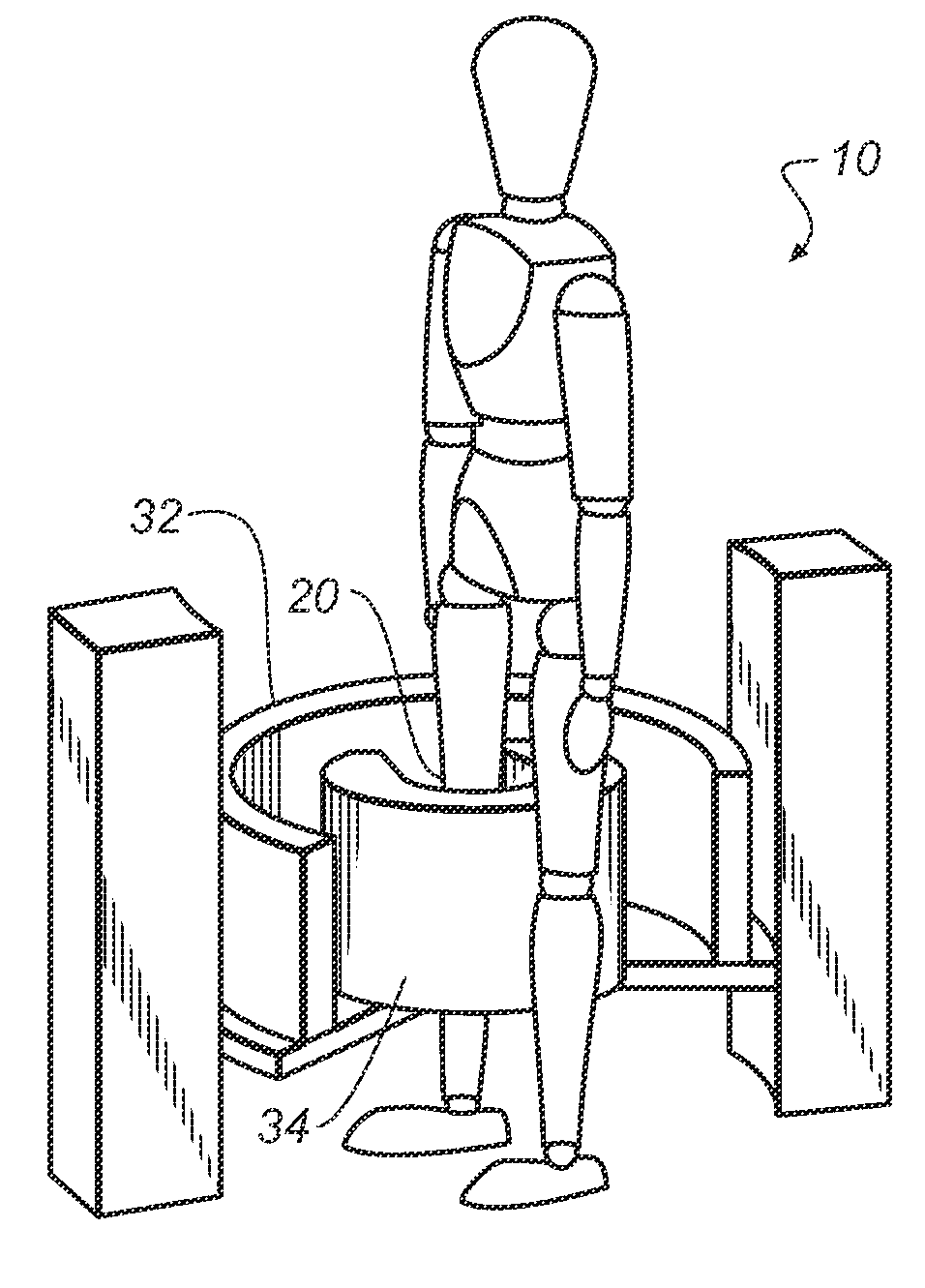
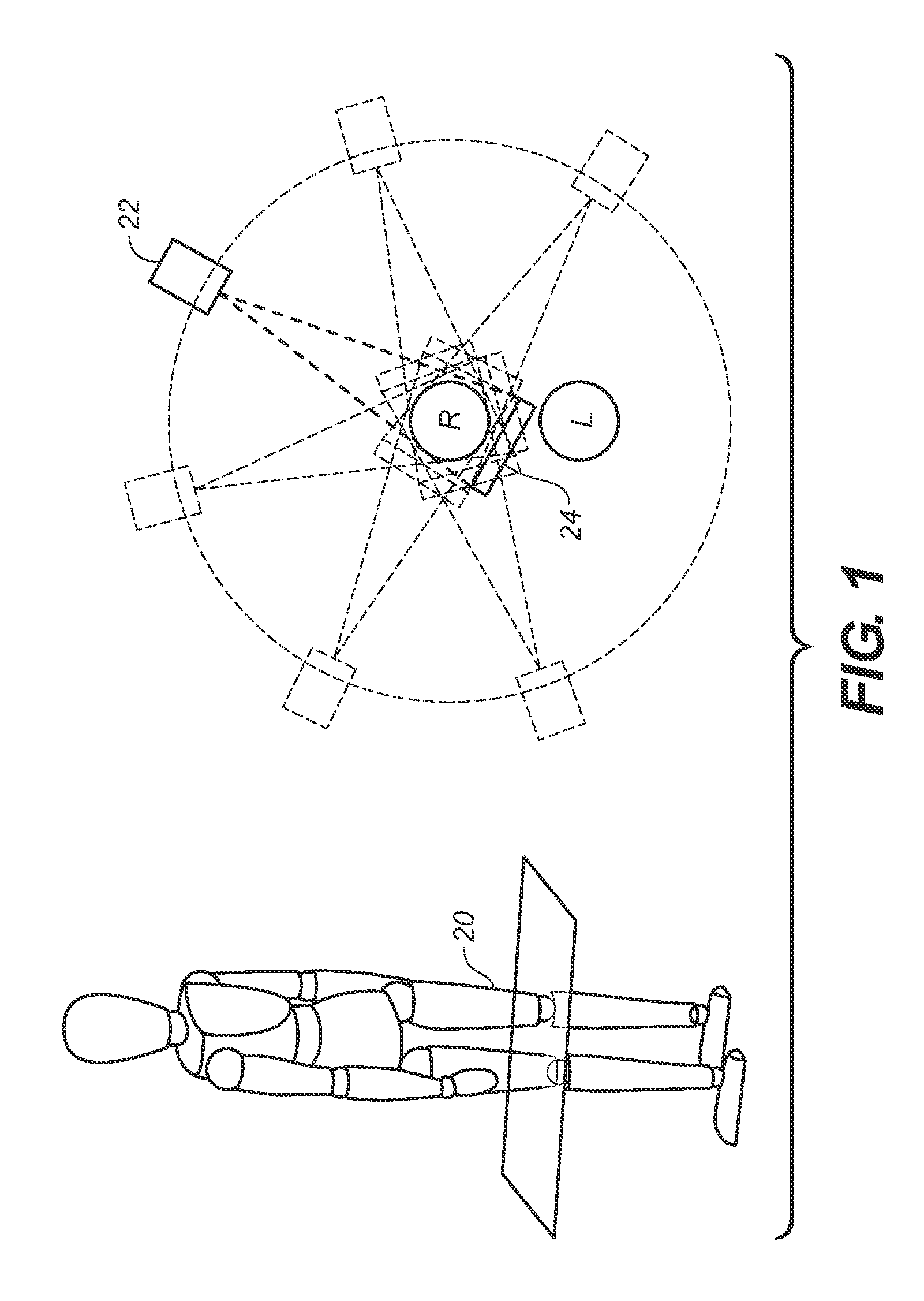
[0042]In the context of the present disclosure, the term “extremity” has its meaning as conventionally understood in diagnostic imaging parlance, referring to knees, legs, ankles, fingers, hands, wrists, elbows, arms, and shoulders and any other anatomical extremity. The term “subject” is used to describe the extremity of the patient that is imaged, such as the “subject leg”, for example. The term “paired extremity” is used in general to refer to any anatomical extremity wherein normally two or more are present on the same patient. In the context of the present invention, the paired extremity is not imaged; only the subject extremity is imaged.

[0043]To describe the present invention in detail, the examples given herein for embodiments of the present...


PUM


Abstract

An apparatus for cone beam computed tomography of an extremity has a digital radiation detector and a first device to move the detector along a circular detector path extending so that the detector moves both at least partially around a first extremity of the patient and between the first extremity and a second, adjacent extremity. The detector path has radius R1 sufficient to position the extremity approximately centered in the detector path. There is a radiation source with a second device to move the source along a concentric circular source path having a radius R2 greater than radius R1, radius R2 sufficiently long to allow adequate radiation exposure of the first extremity for an image capture by the detector. A first circumferential gap in the source path allows the second extremity to be positioned in the first circumferential gap during image capture.

Description

CROSS REFERENCE TO RELATED APPLICATIONS[0001]Priority is claimed from U.S. Ser. No. 61 / 175,091 provisionally filed on May 4, 2009, entitled “Cone Beam Computed Tomography (CBCT) For Extremity Imaging”, in the names of Ian Yorkston et al., incorporated herein by reference.FIELD OF THE INVENTION[0002]The invention relates generally to diagnostic imaging and in particular to cone beam imaging systems used for obtaining volume images of extremities.BACKGROUND OF THE INVENTION[0003]3-D volume imaging has proved to be a valuable diagnostic tool that offers significant advantages over earlier 2-D radiographic imaging techniques for evaluating the condition of internal structures and organs. 3-D imaging of a patient or other subject has been made possible by a number of advancements, including the development of high-speed imaging detectors, such as digital radiography (DR) detectors that enable multiple images to be taken in rapid succession.[0004]Cone beam (CB) computed tomography (CT) (C...

Claims


Application Information

Patent Timeline
Patent Type & Authority Patents(United States)
IPC IPC(8): H05G1/04
CPCA61B6/032A61B6/04A61B6/4085A61B6/035A61B6/505A61B6/03A61B6/466A61B6/4452A61B6/4441
Inventor YORKSTON, JOHNASENTO, ROBERTSIEWERDSEN, JEFFREY H.FOOS, DAVID H.
Owner CARESTREAM HEALTH INC
Why Eureka
Try Eureka