Pellicle for lithography
a lithography and pellicle technology, applied in the field of lithography, can solve the problems of not finding a material with sufficient qualities to meet the demand, haze (incremental foreign material) growing on the mask, and material which is not easily decomposable, so as to reduce the amount of gas released
- Summary
- Abstract
- Description
- Claims
- Application Information
AI Technical Summary
Problems solved by technology
Method used
Image

Examples
examples
[0028]Herein below, some experiments and comparative experiments are described, but these are not to be deemed to restrict the meaning of to the present invention.
experiment 1
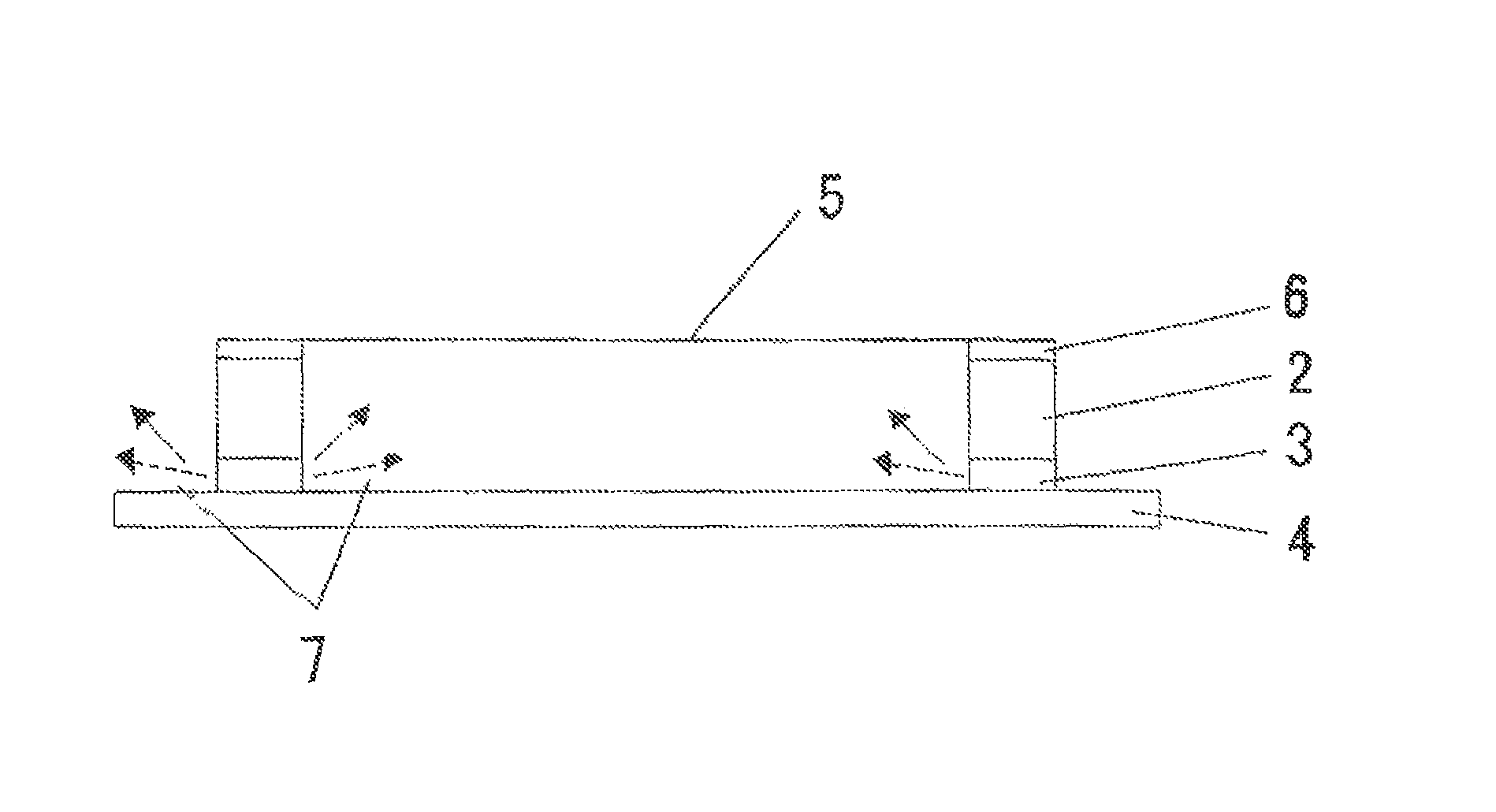
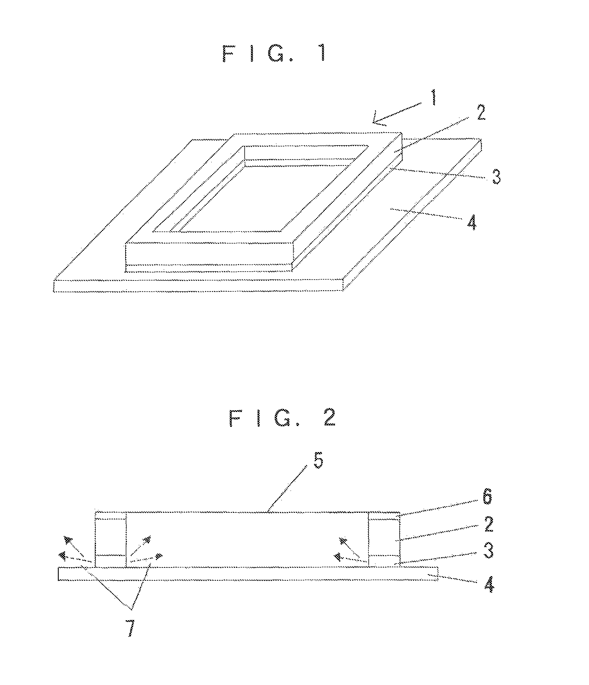
[0029]A pellicle frame made of an aluminum alloy (of which the side lengths were 149 mm and 122 mm, the height 5.8 mm, and the frame bar width 2 mm) was washed in pure water; then, a silicone rubber “KE-1204,” which is a non-agglutinant rubber manufactured by Shin-Etsu Chemical Co., Ltd., was applied to an inner part of one frame face of the pellicle frame along the entire inner edge of the frame face, i.e., endlessly; immediately thereafter the pellicle frame was heated at 150 degrees centigrade by means of electromagnetic induction heating. On this occasion the width of the non-agglutinant belt was 1 mm.
[0030]Subsequently, the entirety of the remainder of the frame face was coated with a silicone agglutinant “KR-3700,” which is an agglutinant paste manufactured by Shin-Etsu Chemical Co., Ltd.; immediately thereafter the pellicle frame was heated at 150 degrees centigrade by means of electromagnetic induction heating. The width of the agglutinant belt was 1 mm.
[0031]Onto the other ...
experiment 2
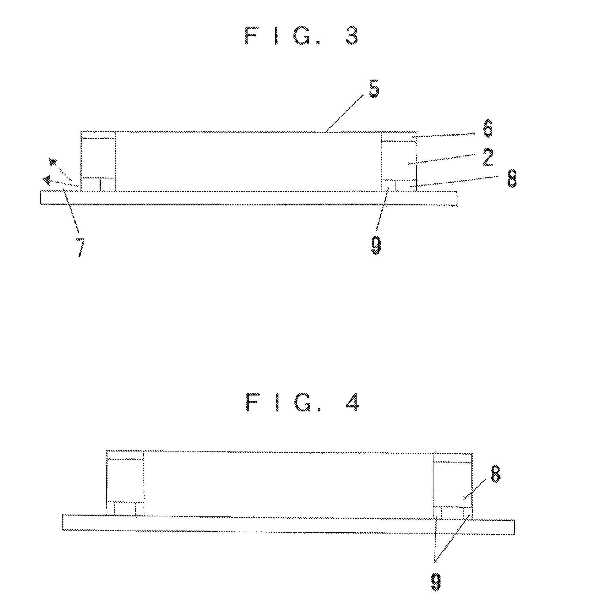
[0035]A pellicle frame made of an aluminum alloy (of which the side lengths were 149 mm and 122 mm, the height 5.8 mm, and the frame bar width 2 mm) was washed in pure water; then, a silicone rubber “KE-1204,” which is a non-agglutinant rubber manufactured by Shin-Etsu Chemical Co., Ltd., was applied to an inner part of one frame face of the pellicle frame along the entire inner edge of the frame face and to an outer part of the same frame face along the entire outer edge of the frame face; immediately thereafter the pellicle frame was heated at 150 degrees centigrade by means of electromagnetic induction heating. On this occasion the widths of the resulting inner non-agglutinant belt and the outer non-agglutinant belt were both 0.5 mm, and that part of the frame face which was between the two belts was free of a coating material.
[0036]Thereafter, a silicone agglutinant “KR-3700,” manufactured by Shin-Etsu Chemical Co., Ltd., was applied to the central part of the frame face between...
PUM
| Property | Measurement | Unit |
|---|---|---|
| width | aaaaa | aaaaa |
| height | aaaaa | aaaaa |
| height | aaaaa | aaaaa |
Abstract
Description
Claims
Application Information
 - R&D
- Intellectual Property
- Life Sciences
- Materials
- Tech Scout
- Unparalleled Data Quality
- Higher Quality Content
- 60% Fewer Hallucinations
Browse by: Latest US Patents, China's latest patents, Technical Efficacy Thesaurus, Application Domain, Technology Topic, Popular Technical Reports.
© 2025 PatSnap. All rights reserved.Legal|Privacy policy|Modern Slavery Act Transparency Statement|Sitemap|About US| Contact US: help@patsnap.com