Multivariate optical elements for nonlinear calibration

a multi-variate, optical element technology, applied in the direction of optical radiation measurement, instruments, spectrophotometry/monochromators, etc., can solve the problems of inability to accurately measure the data relating to one, inability to convert simple light intensity measurement to information, and inability to accurately estimate the accuracy of the estima

Active Publication Date: 2013-01-08
HALLIBURTON ENERGY SERVICES INC
View PDF26 Cites 22 Cited by
  • Summary
  • Abstract
  • Description
  • Claims
  • Application Information

AI Technical Summary

Problems solved by technology

In general, a simple measurement of light intensity is difficult to convert to information because it likely contains interfering data.
It is often impossible to adequately measure the data relating to one of these factors since the contribution of the other factors is unknown.
Depending on the circumstances, however, the estimate may be unacceptably inaccurate since factors other than ethylene may affect the intensity of the wavelength bands.
Unfortunately, however, charge couple devices and their required operational instrumentation are very expensive.
Furthermore, the devices are sensitive to environmental conditions.
The power requirements, cooling requirements, cost, complexity and maintenance requirements of these systems have made them impractical in many applications.
While various implementations of optical computing systems have been developed, and while various calibration methodologies have been developed, no design has emerged that generally encompasses all of the desired characteristics as hereafter presented in accordance with the subject technology.

Method used


Image

  • Multivariate optical elements for nonlinear calibration
  • Multivariate optical elements for nonlinear calibration
  • Multivariate optical elements for nonlinear calibration

Examples


first embodiment

[0052]In accordance with the calibration methodology in accordance with the present technology, rather than calibrating to the analyte concentration, one can calibrate to the antilogarithm of the concentration. This has the effect of producing a y-block data array that is related to the transmission-mode data according to the Beer-Lambert law. This does not fix issues with nonlinear interferences with other components of the sample, but it has been shown to improve the quality of nonlinear calibrations.

second embodiment

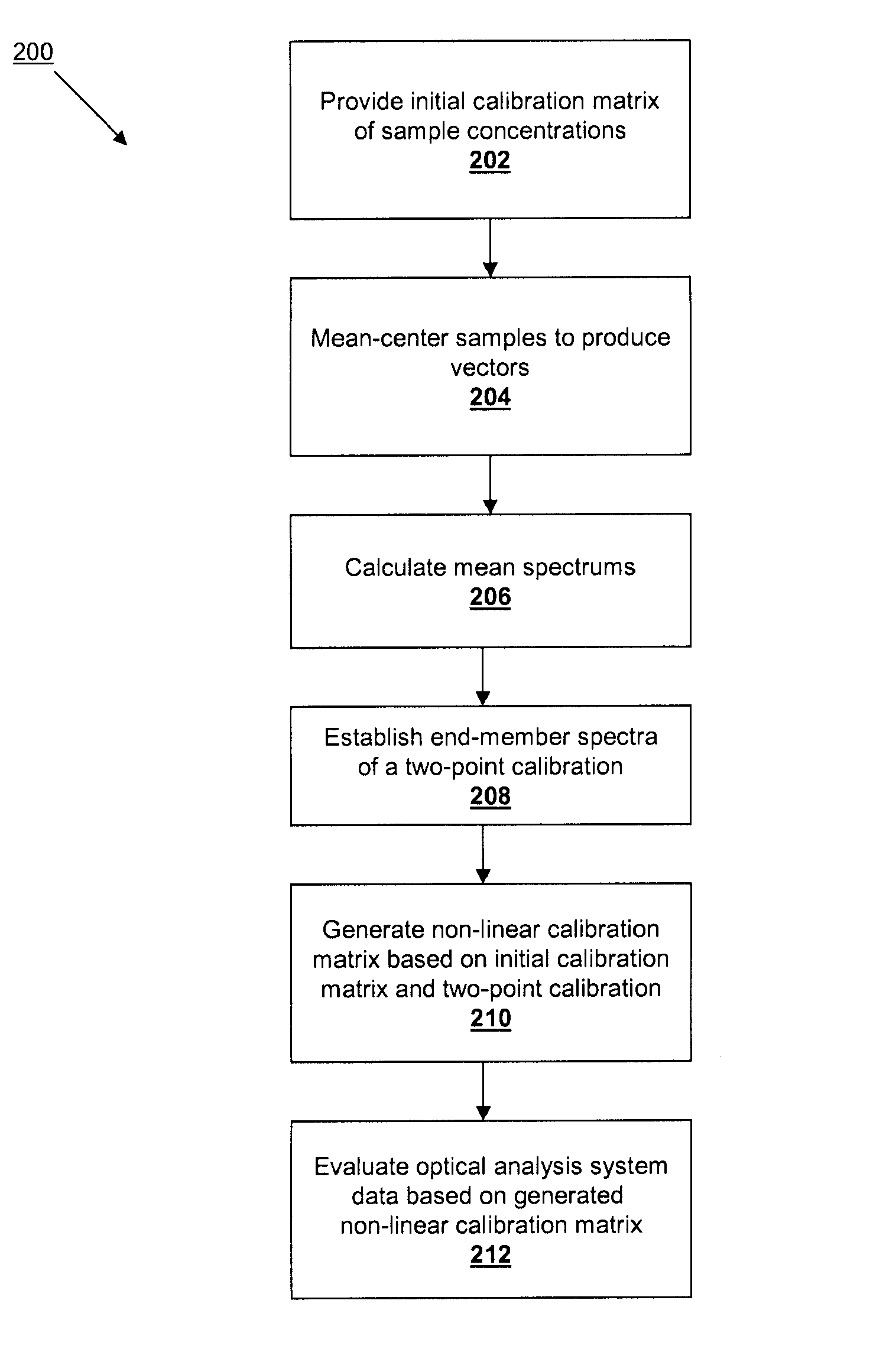
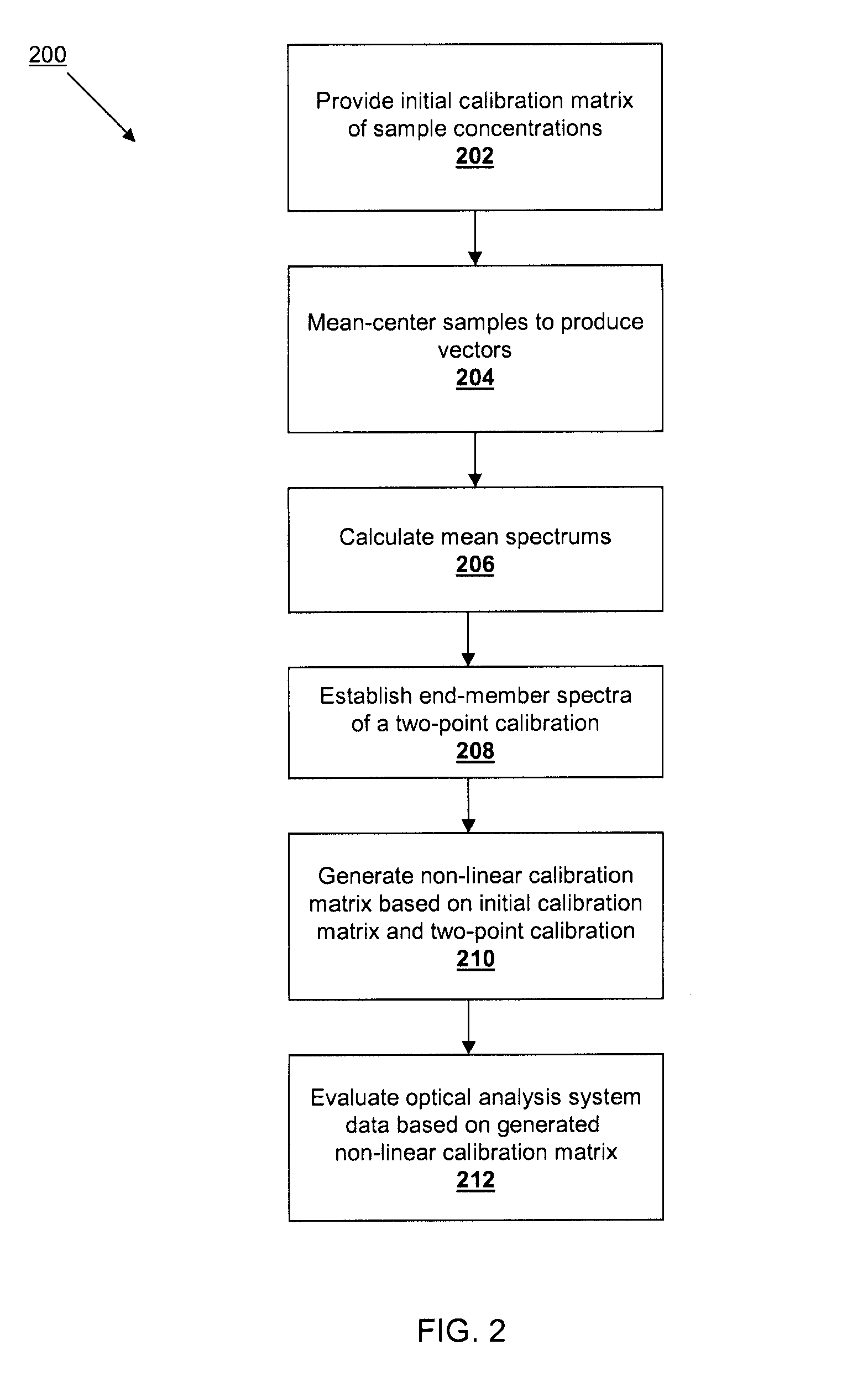
[0053]In accordance with the calibration methodology in accordance with the present technology, one can combine a calibration data set in a way to produce a modified calibration set that includes all the nonlinear spectral artifacts expected of a complex mixture in transmission mode, but that uses only a two-point analyte concentration vector. This results in a calibration that is generally curved if points between the two end-points are included. Such a modified calibration set is created as follows. Consider a conventional 5×5 matrix of sample concentrations with 5 levels of the analyte and 5 of an interferent species. If we take the samples at the same concentration levels of the analyte and perform an operation known as mean-centering (subtracting their average from each), the result is a set of spectra that reflect the vector of interferences for that particular level of analyte concentration. We perform this operation for each of the 5 analyte levels. The mean spectrum of the ...

third embodiment

[0055]In accordance with the calibration methodology in accordance with the present technology, a modification of the design function of the multivariate optical element design suite software is provided. Generally MOEs are designed by iterative solving to a linear function. The process works as follows: (1) An initial MOE design is selected. (2) The spectrum of the MOE is calculated. (3) The dot product of the MOE vector is calculated with each of the calibration spectra. (4) The best linear fit between the calibrated concentrations and the dot products is obtained. (5) This best linear fit is used to determine the standard error of the calibration (SEC). (6) A nonlinear optimization routine is used to optimize this SEC by modifying the design of the MOE.

[0056]In this third embodiment, this algorithm is changed in steps 4 and 5, in which the best quadratic or other nonlinear fitting function is chosen upon which to compute the SEC. If it is considered important to force the functio...


PUM

PropertyMeasurementUnit
frequencyaaaaaaaaaa
frequencyaaaaaaaaaa
optical analysisaaaaaaaaaa

Abstract

The present subject matter is direct to methodologies for calibrating data obtained from an optical analysis system. An initial calibration matrix of sampled analyte concentrations is modified using mean-centering techniques and selection of low and high analyte concentration spectra to produce a two-point calibration. A modified calibration matrix is produced by generating a non-linear calibration matrix by multiplying the initial calibration matrix by the two-point calibration. In an alternate embodiment, an initial multivariate optical element design is modified by iteratively adjusting the design based on standard error of calibration determination based on non-linerly fitted functions.

Description

CROSS-REFERENCE TO RELATED APPLICATIONS[0001]This application claims benefit of U.S. Provisional Patent Application Ser. No. 60 / 903,919, filed Feb. 28, 2007.FIELD OF INVENTION[0002]The present invention relates to the field of multivariate optical element design, manufacture and use. More specifically, the present invention relates to improvements related to the system design, fabrication and operation.BACKGROUND OF THE INVENTION[0003]Light conveys information through data. When light interacts with matter, for example, it carries away information about the physical and chemical properties of the matter. A property of the light, for example, its intensity, may be measured and interpreted to provide information about the matter with which it interacted. That is, the data carried by the light through its intensity may be measured to derive information about the matter. Similarly, in optical communications systems, light data is manipulated to convey information over an optical transmi...

Claims


Application Information

Patent Timeline
Patent Type & Authority Patents(United States)
IPC IPC(8): G01D18/00G06F19/00G06F17/40G01N21/00
CPCG01J3/02G01J3/0232G01J3/12G01J3/28G01N21/274G01N21/31G01N2201/12769
Inventor MYRICK, MICHAEL L.PROFETA, LUISA
Owner HALLIBURTON ENERGY SERVICES INC
Why Eureka
Try Eureka