Side air bag apparatus and manufacturing method of a side air bag

a manufacturing method and side air bag technology, applied in the direction of pedestrian/occupant safety arrangement, vehicular safety arrangments, vehicle components, etc., can solve the problems of reducing the restraining area of the side air bag by a corresponding amount, the crimped portion is constricted, and the air bag is difficult to sew. , to achieve the effect of improving mass productivity, improving air tightness, and improving air tightness

Active Publication Date: 2013-01-22
TOYOTA JIDOSHA KK
View PDF15 Cites 12 Cited by
  • Summary
  • Abstract
  • Description
  • Claims
  • Application Information

AI Technical Summary

Benefits of technology

[0013]With this side air bag apparatus, the partition that separates the upper bag portion from the lower bag portion is made up of the upper regions of the lower base cloth, and formed by sewing together the upper regions of the lower base cloth that has been folded in two about the folding axis. As a result, the side air bag having the upper bag portion and the lower bag portion is easier to sew, which enables mass productivity to be improved, compared with when the partition and the base cloth of the side air bag are separate.
[0014]Also, the tube that extends through the partition to the lower bag portion side and the upper bag portion side so as to distribute inflation gas to the upper bag portion and the lower bag portion is formed in a cylindrical shape by sewing the tube base cloth that has been sewn to the lower base cloth to the upper regions of the lower base cloth, folding that tube base cloth in two toward the front of the vehicle about the folding axis, sewing the resultant front end portions together in the length direction of the tube, and sewing the end edge except for at the insertion hole in the protruding portion closed. Meanwhile, the partition is formed by sewing the upper regions of the lower base cloth that has been folded in two about the folding axis together. As a result, the airtightness between the upper bag portion and the lower bag portion can be improved.
[0015]In this way, with the side air bag apparatus described above, the side air bag having the upper bag portion and lower bag portion that are separated from each other can be sewn easily, which enables mass productivity to be improved, and also enables the airtightness between the upper bag portion and the lower bag portion to be improved.
[0021]With this manufacturing method of an air bag, the upper regions of the lower base cloth are used to form the partition wall. As a result, the side air bag having the upper bag portion and the lower bag portion is easier to sew, which enables mass productivity to be improved, compared with when a tether and the base cloth of the side air bag are separate.
[0022]Also, the tube base cloth is sewn to the bag inner side of the upper regions of the lower base cloth. The areas of the outer peripheries of the upper base cloths and the outer periphery of the lower base cloth that overlap with the tube base cloth are sewn to the tube base cloth. A cylindrical tube is formed by folding the tube base cloth in two about a folding axis, sewing the resultant front end portions together, and sewing the end edge, except for at the insertion hole, of the protruding portion that is exposed from the outer peripheries of the upper base cloths and the lower base cloth, of the tube base cloth closed. The partition is formed by folding the lower base cloth in two about the folding axis and sewing the upper regions together, thereby making it possible to improve the airtightness between the upper bag portion and the lower bag portion.
[0023]In this way, the manufacturing method of a side air bag described above makes the side air bag having the upper bag portion and the lower bag portion easier to sew, which enables mass productivity to be improved, as well as improves the airtightness between the upper bag portion and the lower bag portion.

Problems solved by technology

However, with a structure in which the protruding portion of the side air bag is simply crimped to the inflator using a ring clamp as in the side air bag apparatus described above, the outer periphery of the bag near the crimped portion is constricted and thus will not easily inflate.
As a result, when the side air bag receives a supply of gas from the inflator and consequently inflates and deploys, the pressure of the gas may tend to concentrate near the crimped portion.
The problem with this approach, however, is that the restraining area of the side air bag ends up being decreased by a corresponding amount.

Method used


Image

  • Side air bag apparatus and manufacturing method of a side air bag
  • Side air bag apparatus and manufacturing method of a side air bag
  • Side air bag apparatus and manufacturing method of a side air bag

Examples


Embodiment Construction

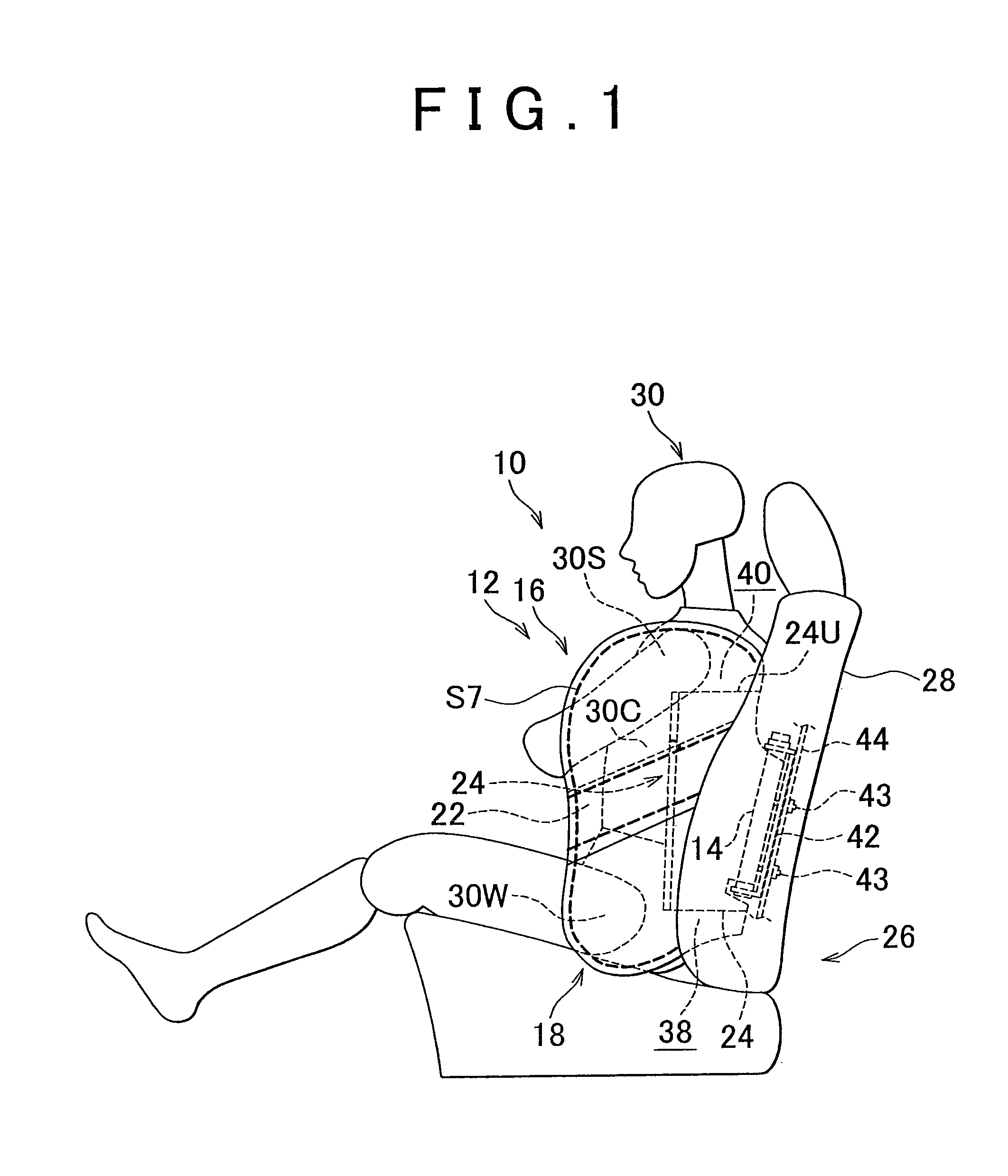
[0042]Example embodiments of the present invention will be described in greater detail below with reference to the accompanying drawings. A side air bag apparatus 10 according to one example embodiment includes a side air bag 12 and an inflator 14, as shown in FIG. 1.

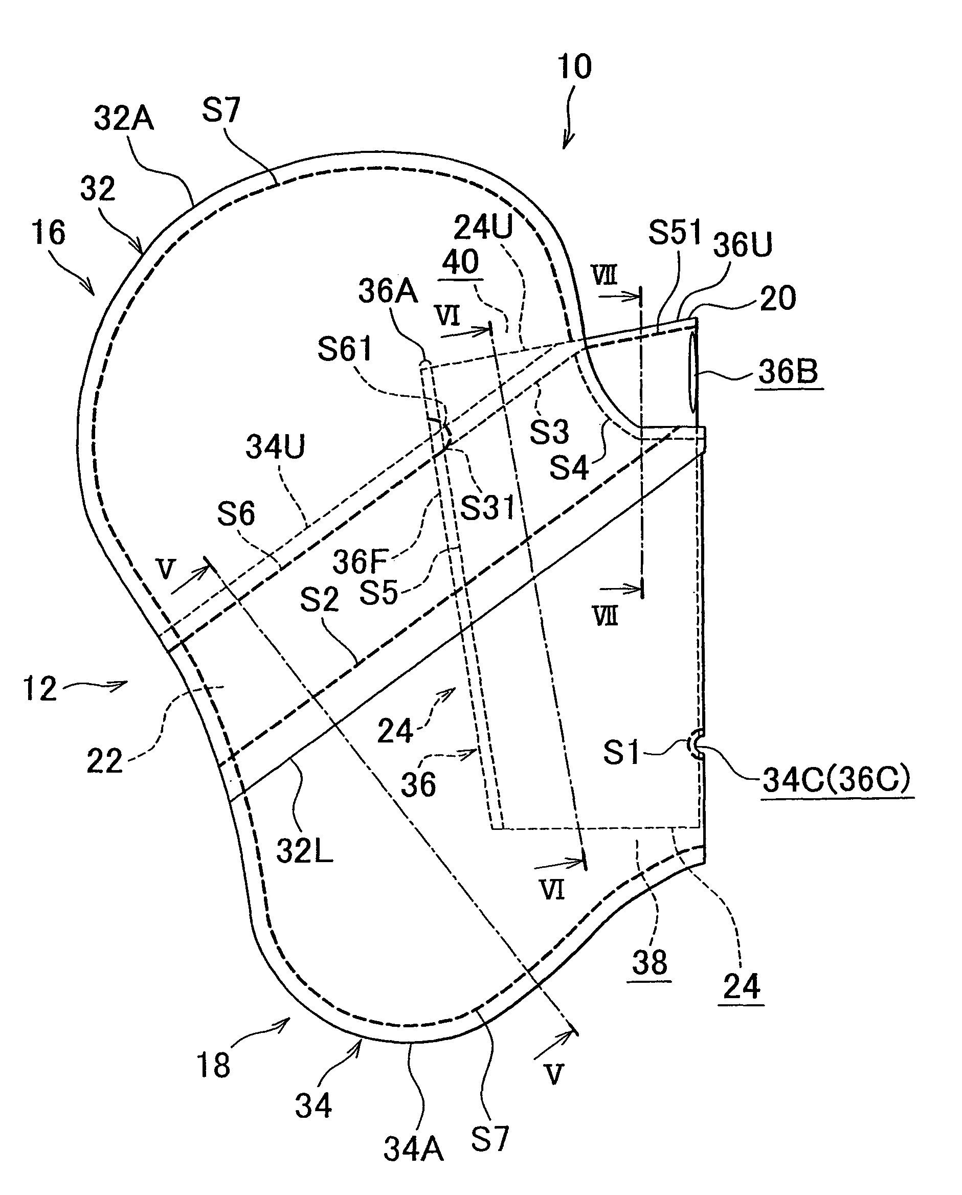
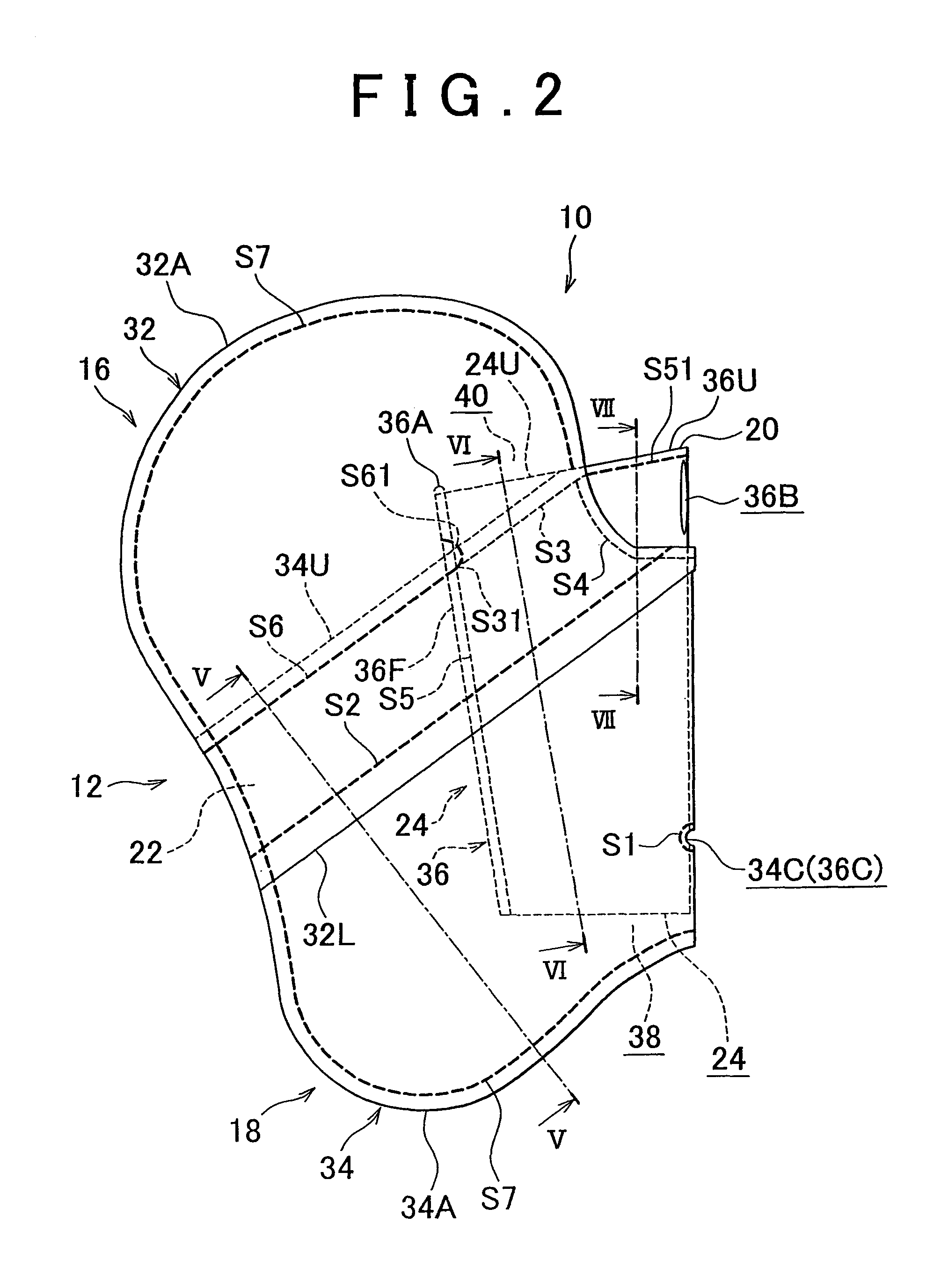
[0043]The side air bag 12 has an upper bag portion 16, a lower bag portion 18, a partition 22, and a tube 24, as shown in FIG. 2. This side air bag 12 is normally stored folded in a side portion of a seat back 28 of a vehicle seat 26, for example, as shown in FIG. 1. During a side collision, gas is supplied to the side air bag 12 from the inflator 14, which causes the side air bag 12 to inflate and deploy next to an occupant 30 seated in the vehicle seat 26. Incidentally, in the drawing, a dummy is shown as the occupant 30.

[0044]The upper bag portion 16 is formed by sewing upper base cloths 32 together, and is an inflating portion that is positioned on the upper side in the vertical direction of the vehicle. The upper b...


PUM


Abstract

A protruding portion that is exposed from the outer peripheries of upper base cloths and a lower base cloth and provided with an insertion hole for inserting an inflator is provided on a portion of a tube base cloth. The inflator is inserted into the side air bag through the insertion hole. The peripheral edge portion of the insertion hole is fixed to the inflator by a clamp. The upper base cloths are not sewn to together in an area where the outer peripheries of the upper base cloths overlap with the tube base cloth, and the lower base cloth is not sewn to itself in an area where the outer periphery of the lower base cloth overlaps with the tube base cloth.

Description

CROSS-REFERENCE TO RELATED APPLICATIONS[0001]This application is a national phase application of International Application No. PCT / IB2010 / 001173, filed May 19, 2010, and claims the priority of Japanese Application No. 2009-121668, filed May 20, 2009, the contents of both of which are incorporated herein by reference.BACKGROUND OF THE INVENTION[0002]1. Field of the Invention[0003]The invention relates to a side air bag apparatus and a manufacturing method of a side air bag.[0004]2. Description of the Related Art[0005]Japanese Patent Application Publication No. 2008-120207 (JP-A-2008-120207) describes a side air bag apparatus in which an inflator is inserted through an insertion hole in a protruding portion (i.e., mounting portion) formed protruding below a side air bag, and the inflator is fastened airtight to the side air bag by fitting and crimping a ring clamp around the outside of the protruding portion.[0006]However, with a structure in which the protruding portion of the side a...

Claims


Application Information

Patent Timeline
Patent Type & Authority Patents(United States)
IPC IPC(8): B60R21/207B60R21/233B60R21/20B60R21/2346
CPCB60R21/23138B60R21/2346B60R21/2171B60R2021/23146B60R2021/23324
Inventor YAMAMOTO, KAZUHITO
Owner TOYOTA JIDOSHA KK
Why Eureka
Try Eureka