

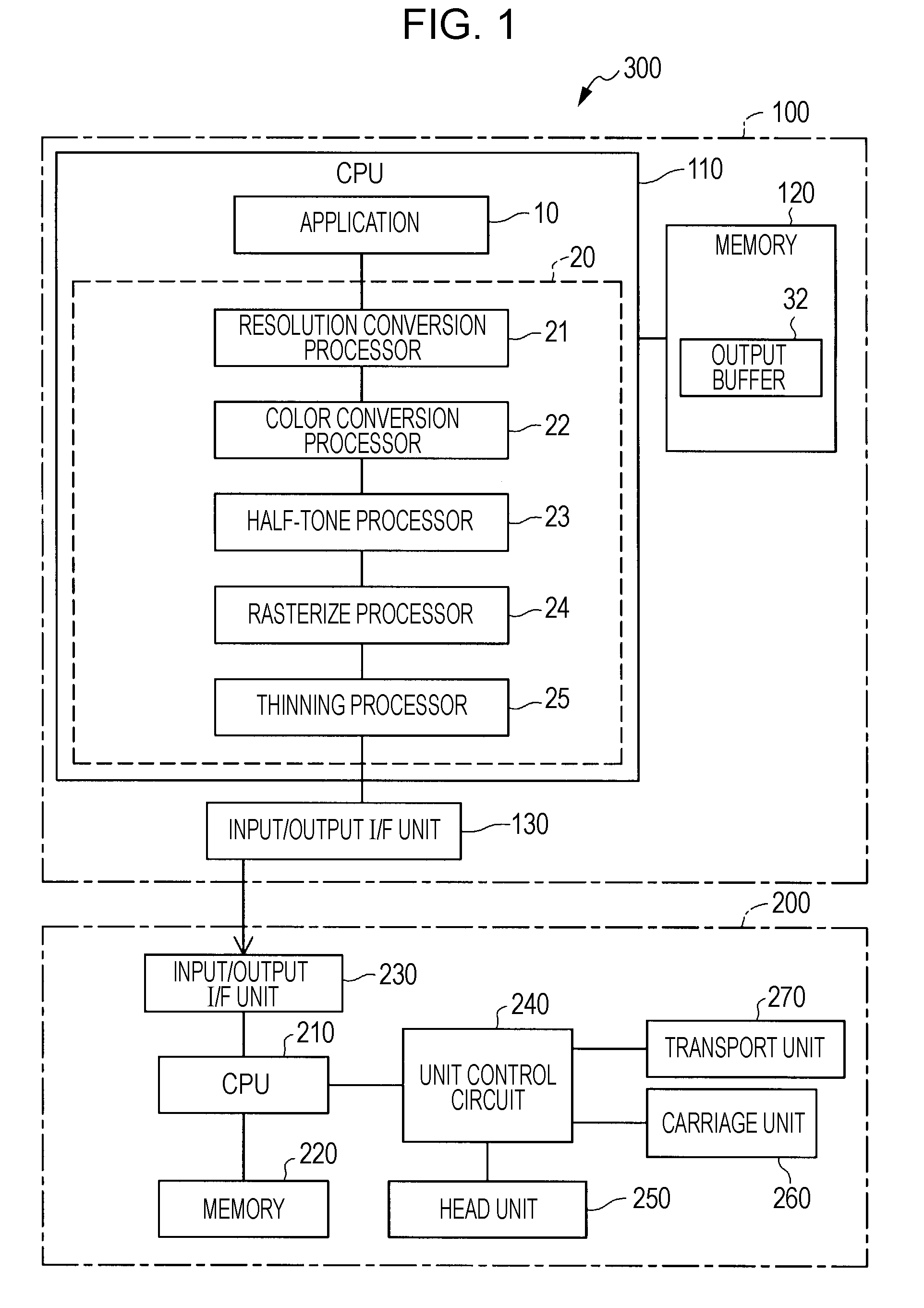
Dot printing system, dot printing method and computer program
a technology of color printing system and computer program, which is applied in the field of color printing system and dot printing method, can solve the problems of excessive deterioration of image quality, and achieve the effect of reducing the amount of colorants and not excessively deteriorating the image quality of the imag
- Summary
- Abstract
- Description
- Claims
- Application Information
AI Technical Summary
Benefits of technology
Problems solved by technology
Method used
Image

Examples
first embodiment
B. First Embodiment
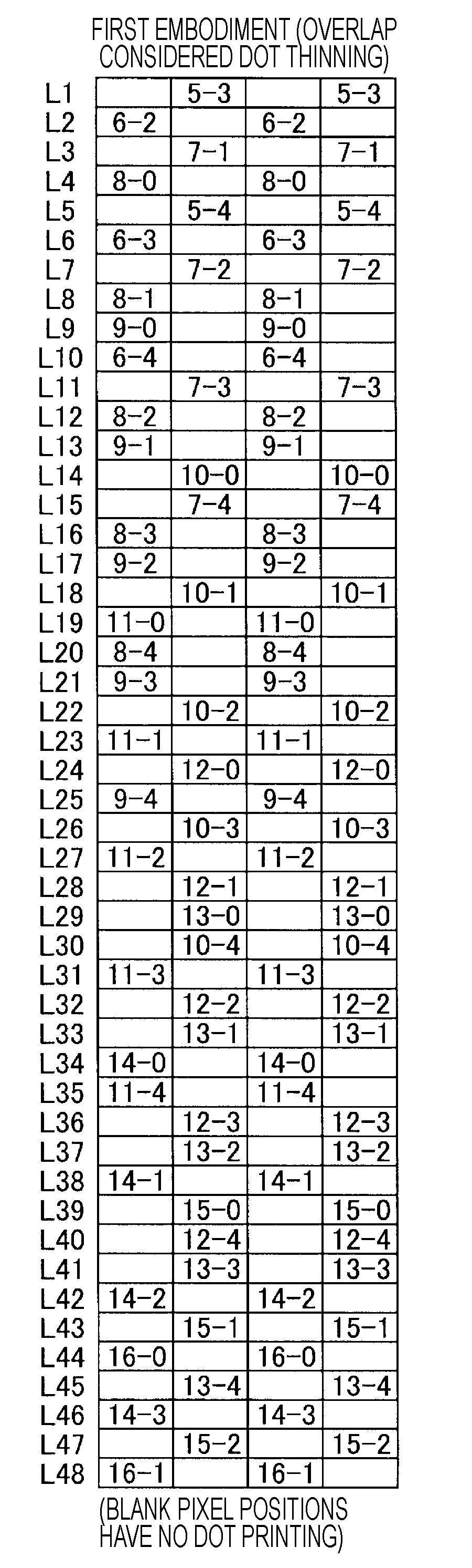
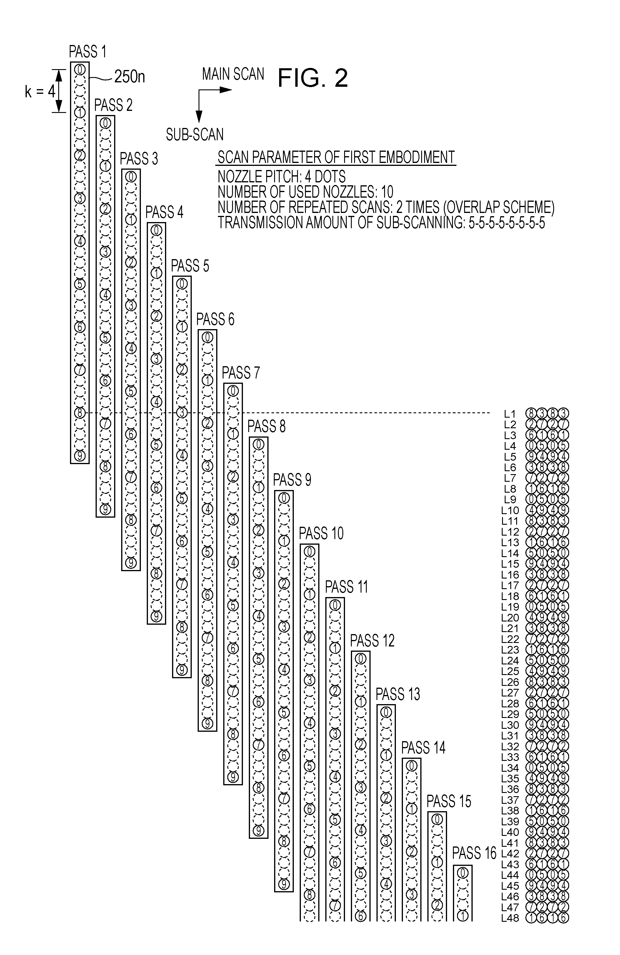
[0038]FIG. 2 is an explanatory view showing a dot printing method in accordance with a first embodiment. Nozzle column 250n mounted in a head unit is shown at the left portion of FIG. 2. The nozzle column 250n has 10 nozzles to discharge one kind of ink (for example, black ink). Nozzle columns for different ink are not shown. While tens to hundreds of nozzles are mounted for each kind of ink in actual printers, a nozzle column having small number of nozzles is described for the sake of convenience of drawing here. Numbers 0-9 attached to each nozzle position are nozzle identification numbers (ID). Pitch k of nozzles in the sub-scanning direction is 180 dpi, for example, and a print pixel pitch is 720 dpi, for example. In this case, nozzle pitch k is 4 [dot]. Generally, it is preferable that pitch k is an integer of 2 or more. The nozzle column 250n prints the dot on the printing medium during the performance of the main scanning in the main scanning direction (lef...
second embodiment
C. Second Embodiment
[0056]FIG. 10 is an explanatory view showing a dot printing method in accordance with a second embodiment. The difference with FIG. 2 is the transmission amount of the sub-scanning only, and other than this, the scanning parameters and apparatus configuration are the same as those of the first embodiment. In a dot printing method of FIG. 10, the transmission amount of sub-scanning is expressed as a repeated pattern of (3 dots, 3 dots, 3 dots, 11 dots). As such, a sub-scanning method that uses the transmission amounts of sub-scanning of plural kinds is referred to as “irregular transmission”. As shown in FIG. 2, meanwhile, a sub-scanning method using a fixed transmission amount of sub-scanning is referred to as “regular transmission”. Like the regular transmission, the irregular transmission is also a scanning method in which dots can be printed in all pixel positions in the zone to be printed.
[0057]FIGS. 11A and 11B are explanatory views showing omitting processe...
modified example 1
D1. Modified Example 1
[0059]As for characteristics of the dot omitting in consideration of overlap, at least one of characteristics 3 and 4 to be described below may be added, in addition to the characteristics 1 and 2 described above.
[0060]Characteristic 3. The omitting process is performed in the zone printed by the large size dots only.
[0061]Characteristic 4. The dots to be omitted are selected from every other dot in the main scanning direction.
[0062]The characteristic 3 means that the omitting process is not performed in a zone where the medium and small size dots are used. The reason is that since the large size dot makes a large overlap with adjacent dots, deterioration of image quality does not occur excessively even though some of large size dots are omitted. Meanwhile, the medium and small size dots tend to make the image quality deteriorate when they are omitted since the medium size dot is slightly overlapped with adjacent dots and the small size dot is hardly overlapped...
PUM
 Abstract
Description
Claims
Application Information