Optical disc recording method and optical disc apparatus

a technology of optical disc and recording method, which is applied in the direction of digital signal error detection/correction, instruments, recording signal processing, etc., can solve the problems that the optical disc recording apparatus cannot perform the tracking servo operation of the feedback method, and the focus servo of the feedback method cannot be performed for the light scribe disc, so as to improve the label printing quality of the disc

Inactive Publication Date: 2010-06-17
HITACHI LG DATA STORAGE KOREA
View PDF6 Cites 1 Cited by
  • Summary
  • Abstract
  • Description
  • Claims
  • Application Information

AI Technical Summary

Benefits of technology

[0013]An aspect of this document is to provide a method of impr

Problems solved by technology

However, since the label plane of the Light Scribe disc does not have the reflection layer and has a very rough plane as compared with the data plane, the error signals enabling the focusing servo of a feedback method are not generated from the label plane.
Accordingly, the focusing servo of a feedback method cannot be performed for the Light Scribe disc, and the focusing servo of a feed forward method is inevitably performed for the Light Scribe disc.
However, since the wobbled lands and grooves for the tracking servo and the random access are not formed in the label plane of a disc for label recording, the optical disc recording apparatus cannot perform the trac

Method used


Image

  • Optical disc recording method and optical disc apparatus
  • Optical disc recording method and optical disc apparatus
  • Optical disc recording method and optical disc apparatus

Examples


Embodiment Construction

[0032]Hereinafter, an optical disc recording method and an optical disc apparatus according to embodiments of this document will be described in detail with reference to the attached drawings.

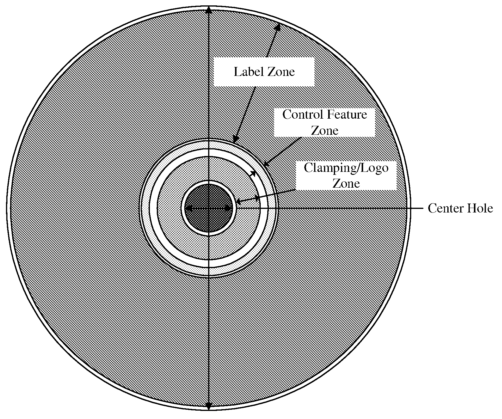
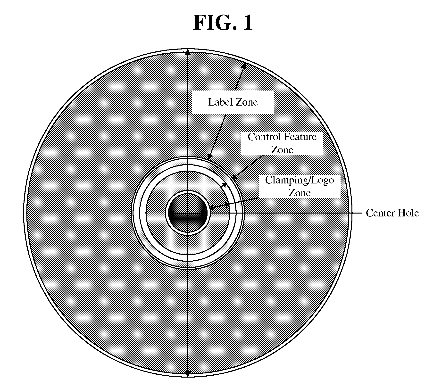
[0033]The layout of a label plane of a LightScribe recording disc is shown in FIG. 1. As shown in FIG. 2, the LightScribe disc includes a Control Feature Zone (i.e., zone including patterns for performing servo in the feed forward method). An index mark area, media ID areas (Media ID Field 1, 2, 3) such as media IDs, and saw-teeth areas are assigned to the Control Feature Zone. The media IDs are classified into discontinuous 3 fields, and the saw-teeth areas are separated from each other with the media ID fields interposed therebetween.

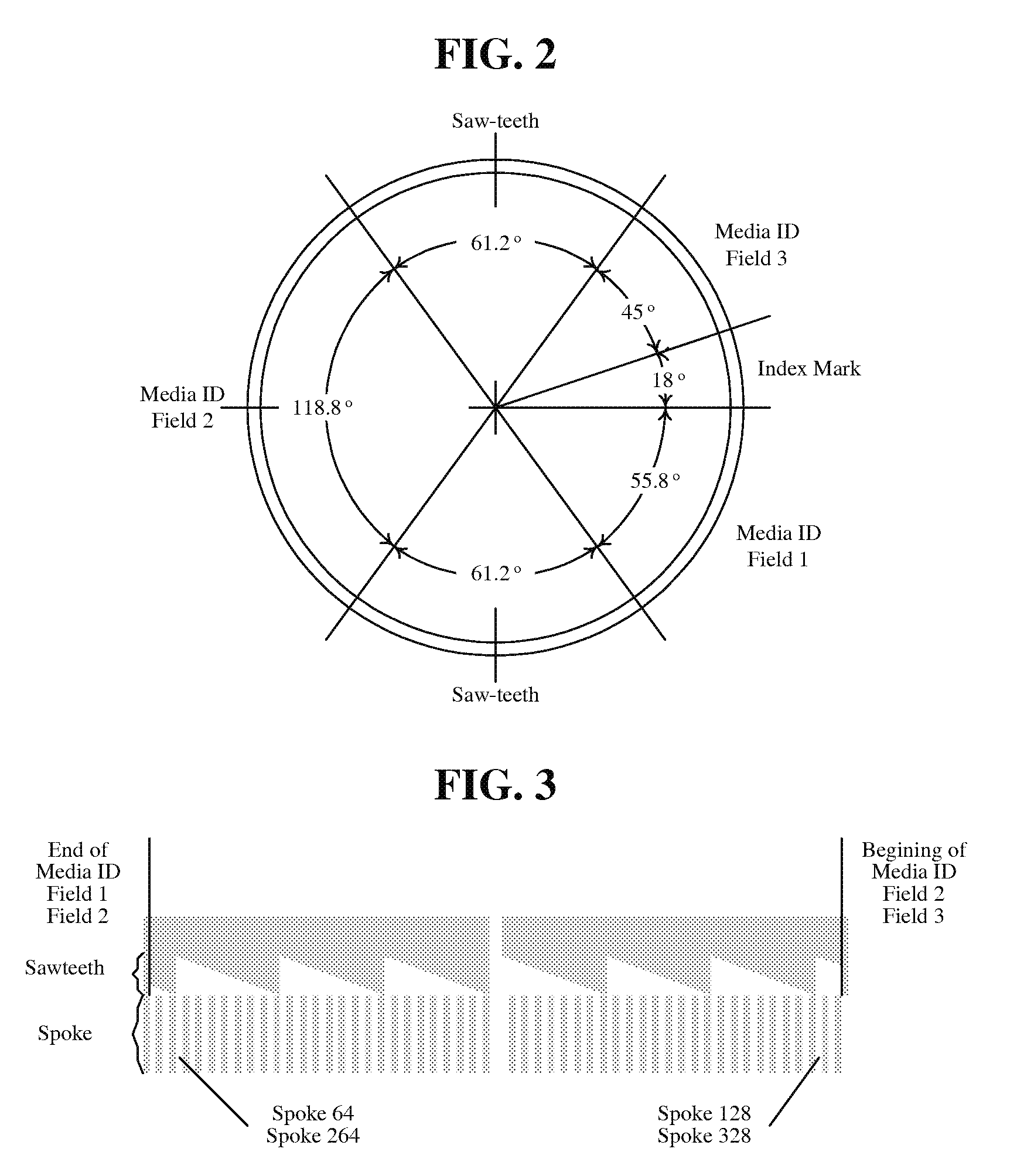
[0034]FIG. 3 shows the saw-teeth area and spokes. The saw-teeth area of 650 in width is separated into two areas facing each other by taking the eccentricity of the disc into consideration. The index marks are used to synchronize spoke 0. The spoke 0 is started ...


PUM


Abstract

This document relates to a method capable of reducing transfer errors of a sled motor for moving an optical pickup to the outer circumference when labels are recorded on a disc. An optical disc recording method may comprise checking a step pattern having a small transfer error in the sled motor, and recording labels on a label plane of an optical disc while driving the sled motor based on the checked step pattern. Step patterns can be classified based on a structure of the sled motor or a unit for driving the sled motor. The step patterns having a small transfer error can be detected in a process of manufacturing an optical disc apparatus and stored in memory of the optical disc apparatus.

Description

[0001]This application claims the benefit of Korean Patent Application No. 10-2008-0128518 filed on Dec. 17, 2008, which is hereby incorporated by reference.BACKGROUND[0002]1. Field[0003]This document relates to an optical disc recording method and, more particularly, to a method capable of reducing transfer errors of a sled motor for moving an optical pickup to the outer circumference when recording labels on a disc.[0004]2. Related Art[0005]An optical disc apparatus and discs for label recording, such as LightScribe discs, enabling label printing on a plane opposite to the data plane on which data are recorded, are being popularized. The plane on which labels are recorded, of a disc for label recording, is called a label plane.[0006]In the data plane of an optical disc, a recording layer in which marks are formed is formed in a disc for recording, pits are formed in a disc for playback and an additional reflection layer are formed. When an optical pickup radiates a laser beam on t...

Claims


Application Information

Patent Timeline
IPC IPC(8): G11B20/18
CPCG11B7/08505G11B7/0037G11B7/0045G11B7/085G11B23/40
Inventor SON, YURAK
Owner HITACHI LG DATA STORAGE KOREA
Why Eureka
Try Eureka