
Content distribution method, encoding method, reception/reproduction method and apparatus, and program

a content distribution and encoding technology, applied in the field of content distribution via a network, can solve the problems of high possibility of packet loss, loss of distributed packets, and video or audio disturbance, and achieve the effect of reducing the probability of data loss

Active Publication Date: 2010-12-21
NEC CORP
View PDF17 Cites 1 Cited by
  • Summary
  • Abstract
  • Description
  • Claims
  • Application Information

AI Technical Summary

Benefits of technology

This approach reduces disturbances caused by transmission errors, minimizes bandwidth usage, and maintains content quality by allowing selection of the lowest compression-rate data or using FEC data for decoding, thus reducing packet loss probability without extra server load.

Problems solved by technology

On an IP network, there is a possibility that distributed packets are lost.
In particular, the possibility of packet loss is higher when the network is wireless.
And, when even a part of content data is lost, a client cannot completely decode videos and audios with the result that the videos or audios are disturbed by interferences or noises or sometimes cannot be reproduced at all.

Method used


Image

  • Content distribution method, encoding method, reception/reproduction method and apparatus, and program
  • Content distribution method, encoding method, reception/reproduction method and apparatus, and program
  • Content distribution method, encoding method, reception/reproduction method and apparatus, and program

Examples


first embodiment

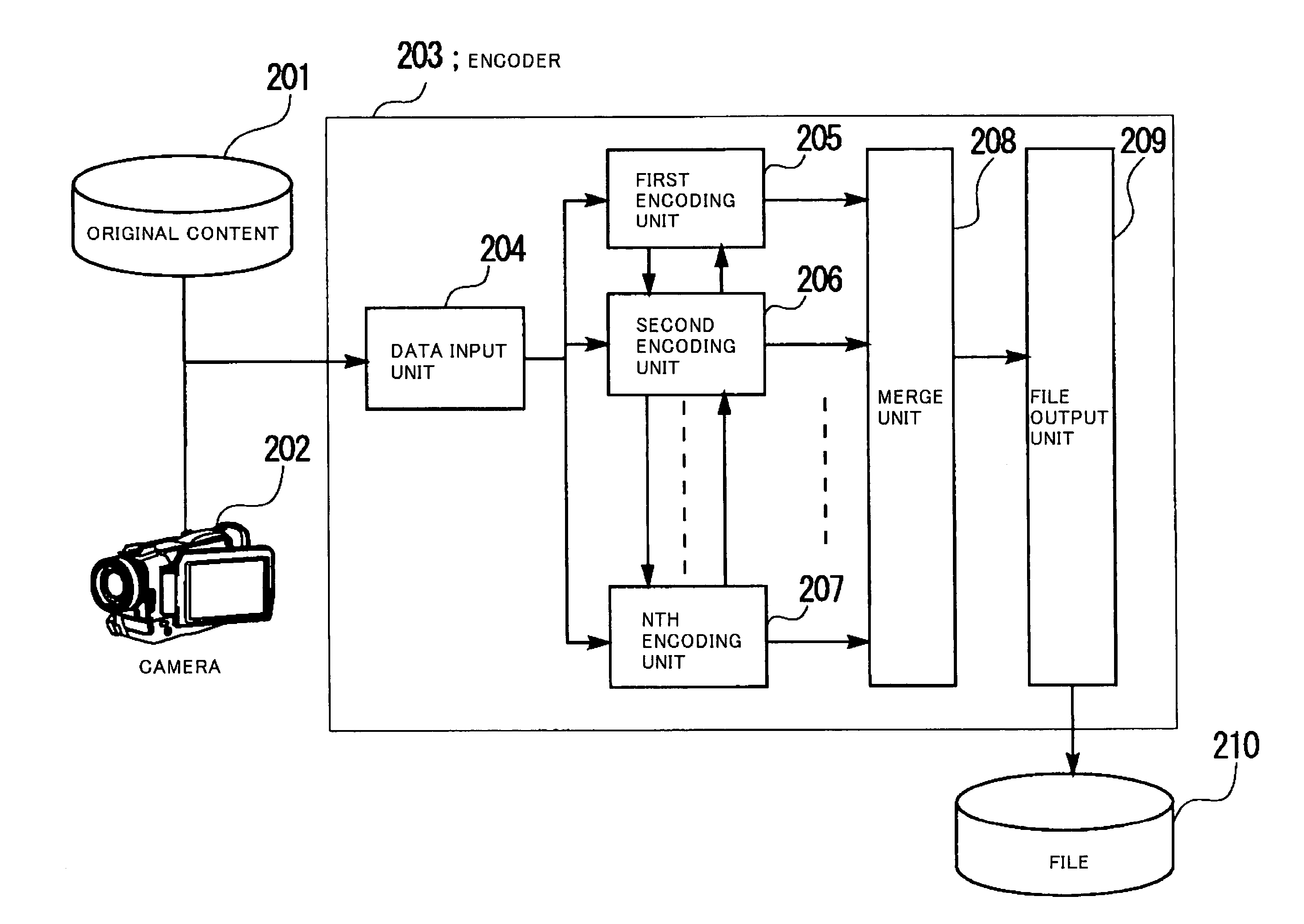
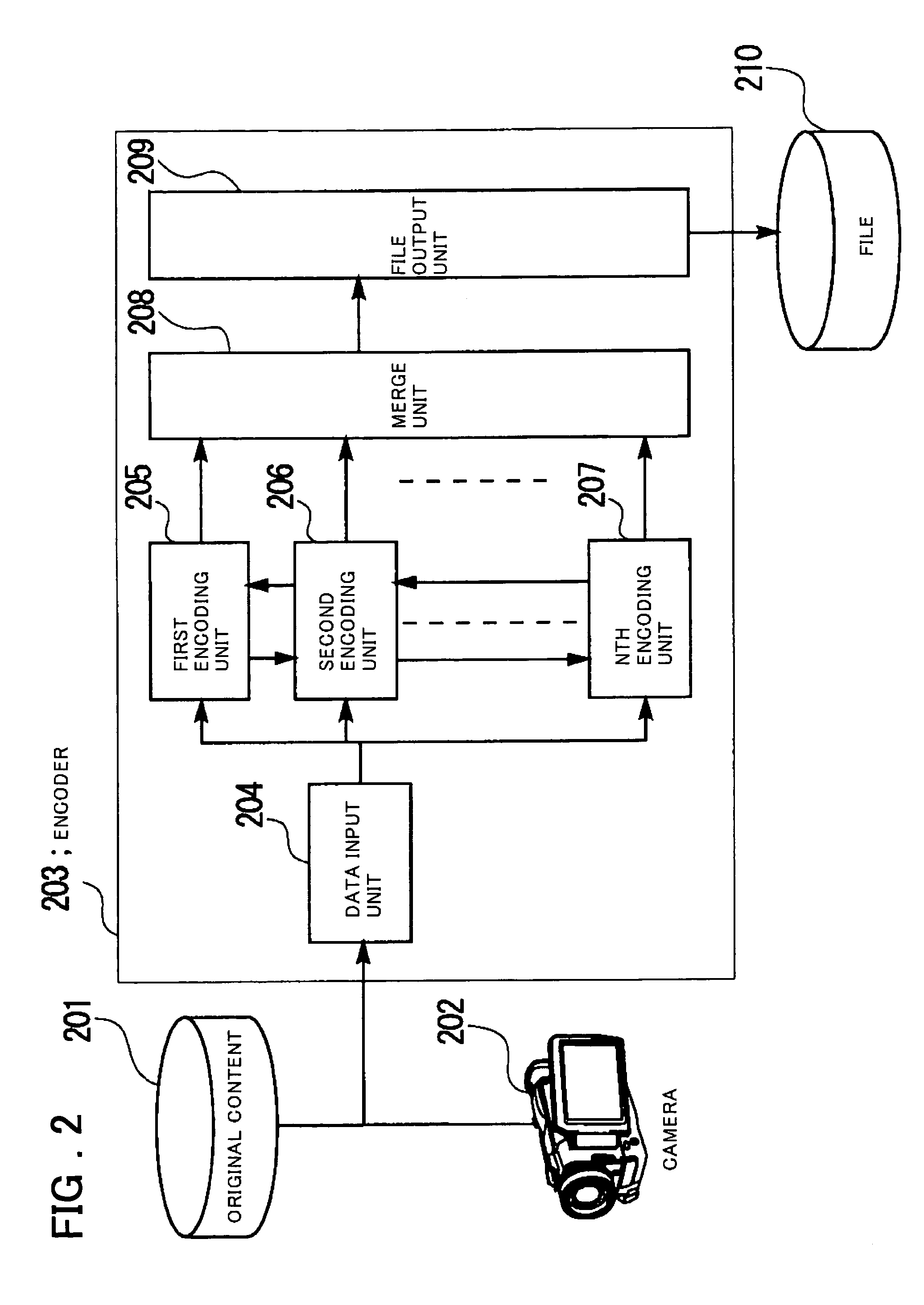
[0164]Next, the first embodiment, described above with reference to FIG. 1 to FIG. 4, will be described below using a specific embodiment. FIG. 6 is a diagram showing the configuration of one embodiment of the encoder 103 in FIG. 1 in which the encoder 203 in FIG. 2 is configured by two encoders. The basic configuration of the present embodiment is similar to that in FIG. 1 except that the encoder 103 has the configuration shown in FIG. 6 instead of the configuration of the encoder 203 in FIG. 2. The distribution server 105 and the client 106 have the same configuration as that of the corresponding unit in FIG. 3 and FIG. 4.

[0165]Referring to FIG. 6, an encoder 603 comprises a data input unit 604, a first encoding unit 605, a second encoding unit 606, a merge unit 607, and a file output unit 608.

[0166]The encoder 603 operates as follows.

[0167]First, moving picture data and / or audio data are input from original content 601 or a camera 602 to the data input unit 604.

[0168]Next, the fi...

second embodiment

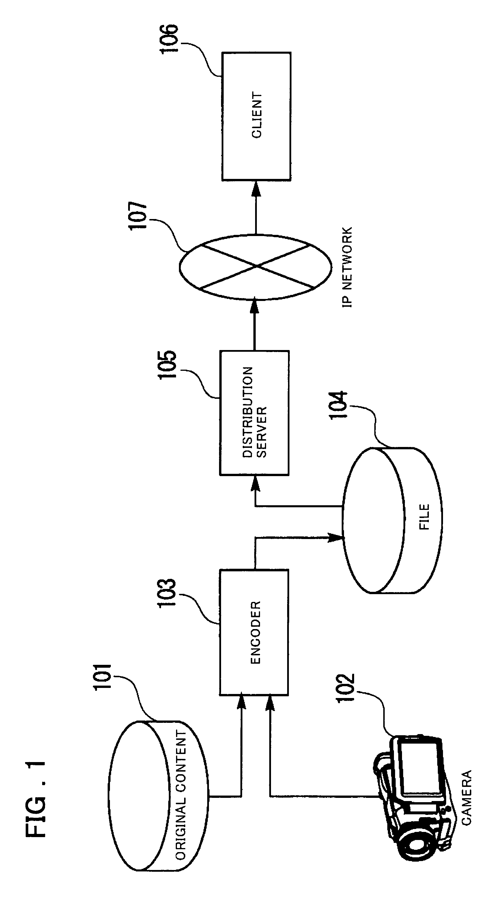
[0188]Next, the second embodiment described above will be described using a specific embodiment. As shown in FIG. 1, the second embodiment of the present invention comprises the encoder 103, the distribution server 105, and the client 106. As described above, the encoder 103 comprises the data input unit 704, the encoding unit 705, the FEC unit 706, the merge unit 707, and the file output unit 708 as shown in FIG. 7. The distribution server 105 comprises the file input unit 303, the file analysis unit 304, the call processing unit 305, the packet generation unit 306, and the distribution unit 307 as shown in FIG. 3. The client 106 comprises the call processing unit 402, the reception unit 403, the data processing unit 404, the data reconstruction unit 405, the decoding unit 406, and the reproduction unit 407 as shown in FIG. 4.

[0189]The encoder 703 in FIG. 7 operates as follows. First, the data input unit 704 receives moving picture and / or audio data from the original content 701 or...


PUM


Abstract

There are provided a content data transmission method, device, and program that minimize serious disturbances in reproduced content on the reception side, caused by a transmission error of encoded data, without sending feedback information from the reception side to the transmission side. When an encoder creates encoded data to be distributed, the encoder creates plural items of encoded data at the same time or creates FEC data at the same time in advance and, when storing the data in a file, stores the data as if the data were one item of encoded data. When a distribution server distributes the data using the file, the plurality of items of encoded data are automatically distributed at the same time and the FEC data is distributed. A client receives the plurality of items of encoded data or the FEC data to reduce the probability of data shortage due to a packet loss and, as a result, the deterioration in the image quality and the audio quality is reduced.

Description

FIELD OF THE INVENTION[0001]The present invention relates to a technology for content distribution via a network, and more particularly to a method for performing transmission of encoded data over a transmission path so as to have the tolerance for data-loss, a method for storing data in a recording device so as to have the tolerance, an encoded data reception and decoding method, and an apparatus, system, and program therefor.BACKGROUND OF THE INVENTION[0002]Recently, the widespread use of the Internet makes content distribution more popular where content, including moving pictures and audios, is distributed and played back via an IP (Internet Protocol) network. In the distribution of this kind, in order to improve the transmission efficiency of for example moving pictures, highly efficient compression encoding scheme based on the inter-frame prediction is used in many cases. In those schemes, predictive parameters, acquired by predicting the encoded images from the temporally prec...

Claims


Application Information

Patent Timeline
Patent Type & Authority Patents(United States)
IPC IPC(8): H03M13/00H04L1/00H04L1/08
CPCH04L1/0041H04L1/08H04L1/00H04L1/22
Inventor MIZUNO, DAISUKEDEI, HIROAKIOZAWA, KAZUNORI
Owner NEC CORP
Learn More