Check patentability & draft patents in minutes with Patsnap Eureka AI!

Post processing apparatus and image forming system using the same apparatus

a technology of image forming system and post processing apparatus, which is applied in the direction of electrographic process apparatus, instruments, optics, etc., can solve the problems of generating more impact, reducing the number of recording sheets to be processed, and adversely affecting mechanical vibration and impa

Active Publication Date: 2013-01-29
KONICA MINOLTA BUSINESS TECH INC
View PDF17 Cites 0 Cited by
  • Summary
  • Abstract
  • Description
  • Claims
  • Application Information

AI Technical Summary

Benefits of technology

This configuration allows for precise alignment and secure positioning of the apparatuses, effectively absorbs vibrations and impacts, maintaining image reading accuracy even when processing large volumes of sheets, without the need for additional grounding components, thus reducing manufacturing costs.

Problems solved by technology

However, during binding operation, hole-punching operation, and folding operation, mechanical vibration and impact are adversely generated, wherein the impact is specifically and greatly generated during the binding operation.
Further, due to the speeding up of the image forming apparatus, the number of the recording sheets to be processed becomes greater, the more impact is generated.
If the image forming apparatus and the post processing apparatus, disclosed in Unexamined Japanese Patent Application Publication No. 2002-128369, are combined, most of the vibration and the impact, generated in the post processing operation of the post processing apparatus, reach the image forming apparatus, which result in the reduction of an image reading accuracy.
However, according to the technology of the latter Patent Application, the vibration and the impact, generated by the post processing apparatus, directly reach the image forming section, and since the image reading section has been mounted on the image forming section, when a bundle of a large number of recording sheets are to be finished, the image reading section adversely receives no small effect, though the vibration control member has been used.
Further, if the vibration control member is mounted in the vertical direction, the weight of image reading section and a document feeding device, both mounted on the vibration control member, compresses the vibration control section, which results in the reduced effect of the vibration control member.
Still further, based on the difference of the weight of units to be mounted on the vibration control member, the effect of the vibration control member changes, so that the units to be mounted are limited, which is a major problem.

Method used


Image

  • Post processing apparatus and image forming system using the same apparatus
  • Post processing apparatus and image forming system using the same apparatus
  • Post processing apparatus and image forming system using the same apparatus

Examples


Embodiment Construction

[0021]The present invention will now be detailed, while referring to an embodiment shown in the figures, but the present invention is not limited to the embodiment detailed below.

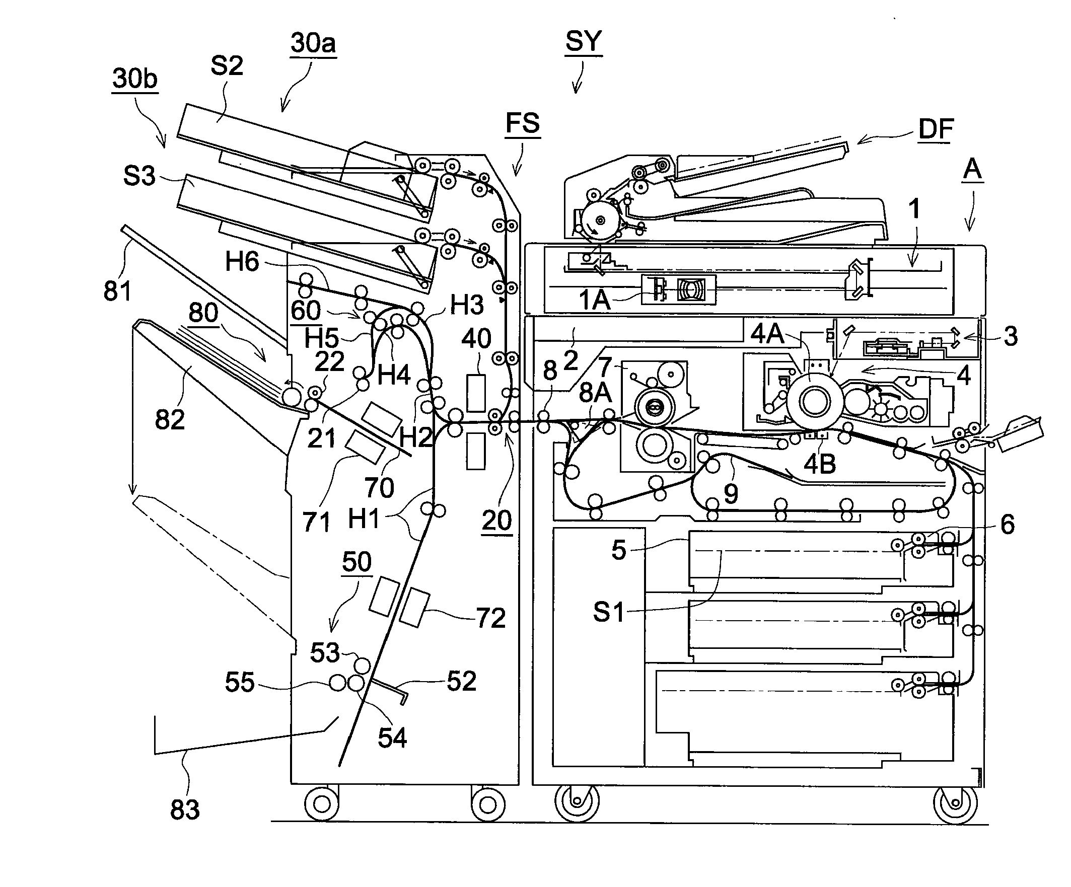
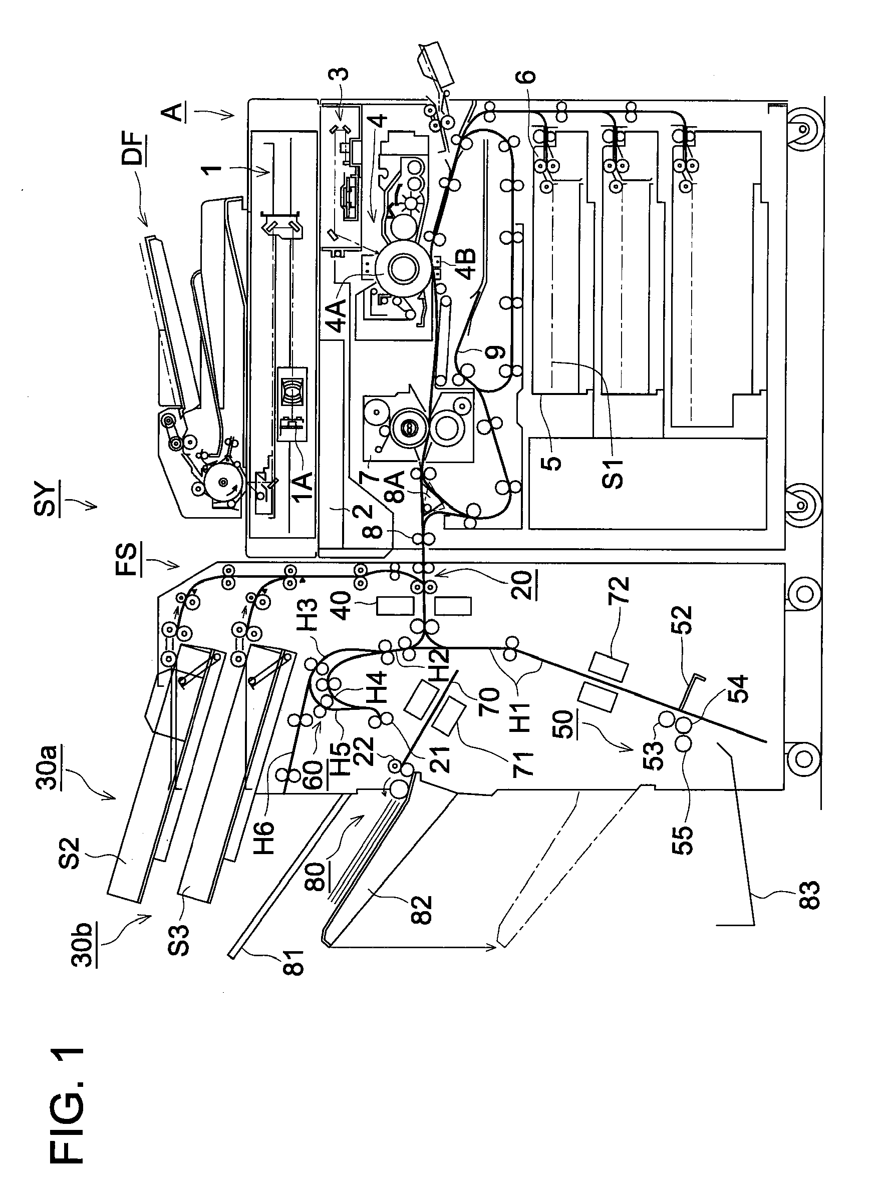
[0022]FIG. 1 is the total schematic drawing of image forming system SY, relating to the present invention. Image forming system SY of the present invention includes image forming apparatus “A” to be placed on the floor, and post processing apparatus FS, combined to the downstream side of image forming apparatus “A”, also placed on the floor with respect to the sheet conveyance direction, so that post processing apparatus FS performs the post processing operation onto the plurality of the recording sheets ejected from image forming apparatus “A”. Automatic document feeding device DF is mounted on image forming apparatus “A”, and post processing apparatus FS is combined to the downstream side of image forming apparatus “A”.

[General Description of Image Forming Apparatus “A”]

[0023]Image forming apparatus “A” i...


PUM


Abstract

A post processing apparatus, placed on a floor, and placed next to a downstream side of an image forming apparatus also placed on the floor in a sheet conveyance direction, to perform a post processing operation onto sheets ejected from the image forming apparatus, including a plurality of joining sections to join the image forming apparatus, wherein the plurality of the joining sections include an elastic member.

Description

CROSS REFERENCE TO RELATED APPLICATION[0001]This application is based on Japanese Patent Application No. 2009-004435 filed on Jan. 13, 2009, with the Japanese Patent Office, the entire content of which is hereby incorporated by reference.TECHNICAL FIELD[0002]The present invention relates to a post processing apparatus which conducts a post processing process onto a recording sheet, and an image forming system which includes the post processing apparatus, and an image forming apparatus which forms an image on the recording sheet, and conveys the recording sheet carrying the formed image to the post processing apparatus.BACKGROUND OF THE INVENTION[0003]In recent years, various post processing apparatuses have been developed, which conduct various post processing processes, such as a hole-punching process, a sheet-folding process, and a sheet-binding process, onto sheets which carries images formed by an image forming apparatus, such as an electro-photographic copying device, a printin...

Claims


Application Information

Patent Timeline
Patent Type & Authority Patents(United States)
IPC IPC(8): G03G15/00
CPCG03G15/6538G03G15/6552
Inventor NIIZUMA, MASATO
Owner KONICA MINOLTA BUSINESS TECH INC
Features
  • R&D
  • Intellectual Property
  • Life Sciences
  • Materials
  • Tech Scout
  • Unparalleled Data Quality
  • Higher Quality Content
  • 60% Fewer Hallucinations
Learn More