Golf ball

a golf ball and ball technology, applied in the field of golf balls, can solve the problems of inability to contribute to resilience performance, inability to reduce the hardness difference (h4h3) of the envelope layer, and inability to suppress spin

Active Publication Date: 2013-02-05
SUMITOMO RUBBER IND LTD
View PDF18 Cites 6 Cited by
  • Summary
  • Abstract
  • Description
  • Claims
  • Application Information

AI Technical Summary

Benefits of technology

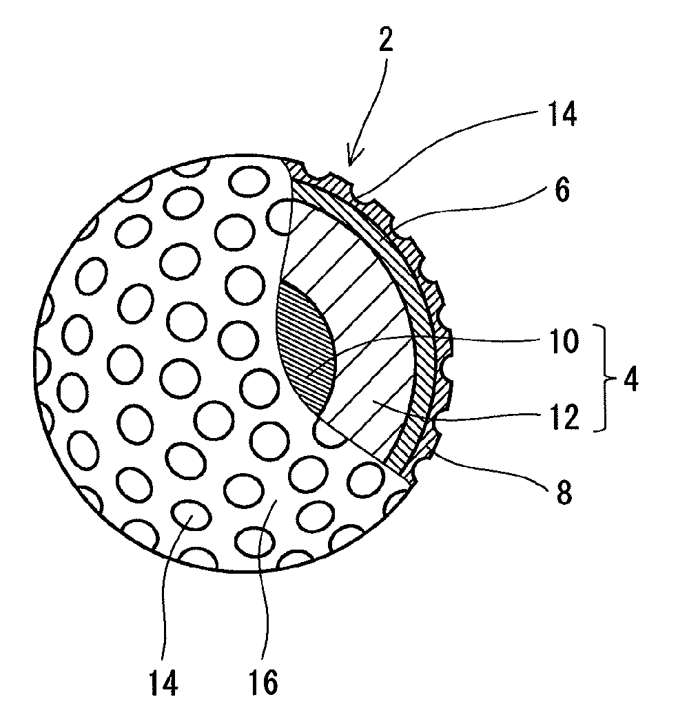
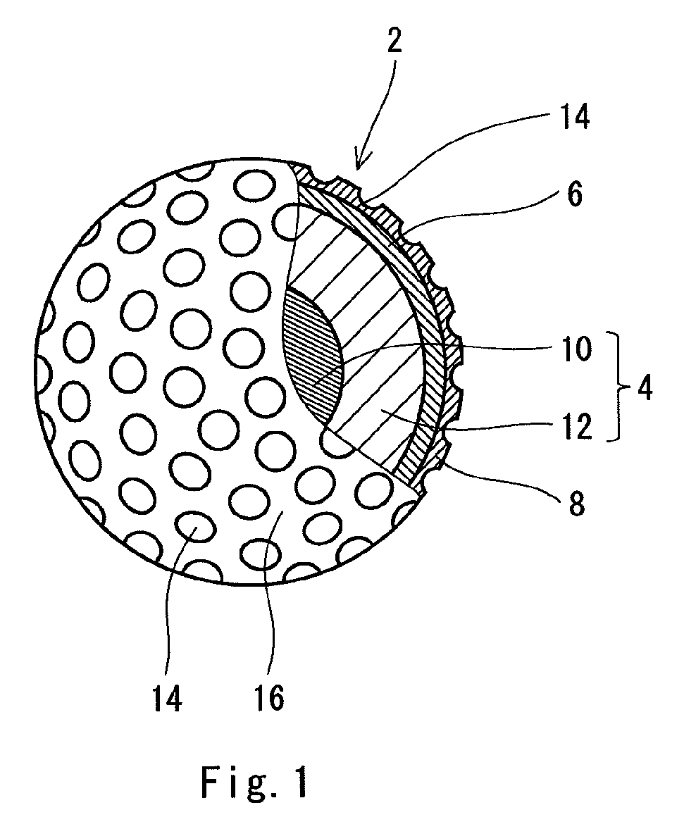
The present invention is a golf ball with a unique structure that achieves both hardness and resilience. The ball has a small center with low hardness and a flexible cover with high rigidity, resulting in an outer-hard / inner-soft structure. This structure has excellent hardness continuity, suppresses spin, and allows for smooth flight. The hollow center and highly elastic cover work together to achieve the desired structure and performance. Overall, the golf ball has a unique and improved design that enhances its performance and resilience.

Problems solved by technology

The step impairs suppression of spin.
The flexible center impairs resilience.
The hollow part cannot contribute to resilience performance.
The flight performance of the golf ball is insufficient.
In a golf ball having an outer-hard / inner-soft structure due to a cover with a high rigidity, the cover impairs feel at impact.
A cover with a high rigidity due to an ionomer resin with a high acid content has inferior durability.
A cover having a high rigidity due to an ionomer resin with a high degree of neutralization has inferior moldability.

Method used


Image

  • Golf ball
  • Golf ball
  • Golf ball

Examples


experiment 1

[Experiment 1]

[Example 1]

[0205]A rubber composition (a) was obtained by kneading 100 parts by weight of a high-cis polybutadiene (trade name “BR-730”, available from JSR Corporation), 5 parts by weight of zinc oxide, an appropriate amount of barium sulfate, 10 parts by weight of silica (trade name “Nipsil AQ”, available from Tosoh Silica Corporation), 2.20 parts by weight of a sulfenamide type vulcanization accelerator (the aforementioned “Nocceler CZ”), 2.26 parts by weight of a guanidine type vulcanization accelerator (the aforementioned “Soxinol DG”), and 3.4 parts by weight of sulfur. The rubber composition (a) was placed into a mold that included upper and lower mold halves each having a hemispherical cavity, and heated at 150° C. for 5 minutes to obtain a center with a diameter of 10 mm.

[0206]A rubber composition (f) was obtained by kneading 100 parts by weight of a high-cis polybutadiene (the aforementioned “BR-730”), 29 parts by weight of zinc diacrylate, 5 parts by weight o...

experiment 2

[Experiment 2]

[Example 12]

[0223]A rubber composition (a) was obtained by kneading 50 parts by weight of a high-cis polybutadiene (trade name “BR-730”, available from JSR Corporation), 50 parts by weight of a natural rubber (KR-7), 5 parts by weight of zinc oxide, an appropriate amount of a clay, 5 parts by weight of silica (trade name “Nipsil AQ”, available from Tosoh Silica Corporation), 2.20 parts by weight of a sulfenamide type vulcanization accelerator (the aforementioned “Nocceler CZ”), 2.26 parts by weight of a guanidine type vulcanization accelerator (the aforementioned “Soxinol DG”), and 3.4 parts by weight of sulfur. The rubber composition (a) was placed into the mold shown in FIG. 3, to obtain a semi-crosslinked half shell. Ammonium chloride, sodium nitrite, and water were put into the half shell. A rubber cement in which the rubber composition (a) was dissolved in a solvent was applied to a joining surface of the half shell. The half shell was fitted with another half she...


PUM


Abstract

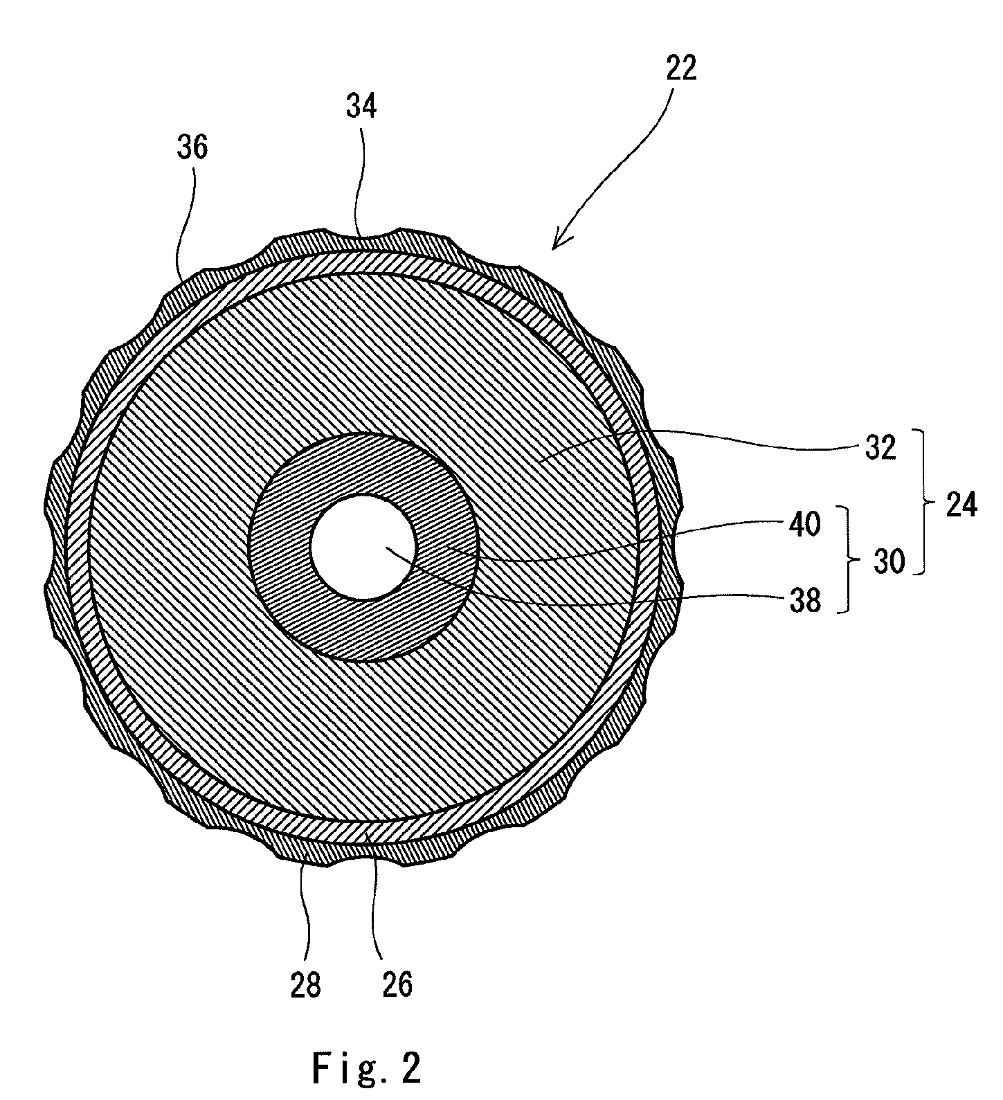
A golf ball 2 includes a spherical core 4, a mid layer 6 positioned outside the core 4, and a cover 8 positioned outside the mid layer 6. The core 4 includes a spherical center 10 and an envelope layer 12 positioned outside the center 10. The center 10 has a diameter of 1 mm or greater and 15 mm or less. The center 10 has a JIS-C hardness H1, at its central point, of 20 or greater and 50 or less. The difference (H4−H3) between the JIS-C hardness H4 of the core 4 at its surface and the JIS-C hardness H3 of the envelope layer 12 at its innermost portion is equal to or greater than 10. The cover 8 has a flexural modulus of 300 MPa or greater and 1000 MPa or less, and has a tensile modulus of 400 MPa or greater and 1500 MPa or less.

Description

[0001]This application claims priority on Patent Application No. 2008-326780 filed in JAPAN on Dec. 24, 2008 and Patent Application No. 2008-327140 filed in JAPAN on Dec. 24, 2008. The entire contents of these Japanese Patent Applications are hereby incorporated by reference.BACKGROUND OF THE INVENTION[0002]1. Field of the Invention[0003]The present invention relates to golf balls. Specifically, the present invention relates to multi-piece golf balls including a center, an envelope layer, and a cover.[0004]2. Description of the Related Art[0005]Golf players' foremost requirement for golf balls is flight performance. Golf players place importance on flight performance with a driver, a long iron, and a middle iron. Flight performance correlates with the resilience performance of a golf ball. When a golf ball with excellent resilience performance is hit, the golf ball flies at a high speed, thereby achieving a long flight distance. Flight performance also correlates with a spin rate. F...

Claims


Application Information

Patent Timeline
Patent Type & Authority Patents(United States)
IPC IPC(8): A63B37/06
CPCA63B37/0003A63B37/0037A63B37/0062A63B37/0064A63B37/0076A63B37/0092A63B37/00622A63B37/00621
Inventor NAKAMURA, HIROTAKAOHAMA, KEIJIISOAGAWA, KAZUHIKOOKABE, SATOKO
Owner SUMITOMO RUBBER IND LTD
Why Eureka
Try Eureka