
Image forming apparatus and image forming unit

a technology of image forming apparatus and forming unit, which is applied in the direction of electrographic process apparatus, instruments, corona discharge, etc., can solve problems such as operability, and achieve the effect of improving operability and efficiently suppressing the adhesion of foreign substances

Active Publication Date: 2013-02-05
BROTHER KOGYO KK
View PDF9 Cites 8 Cited by
  • Summary
  • Abstract
  • Description
  • Claims
  • Application Information

AI Technical Summary

Benefits of technology

[0007]Therefore, an object of the invention is to provide an image forming apparatus and an image forming unit capable of improving operability at the time of cleaning an electric discharge member while efficiently suppressing adhesion of a foreign substance to the electric discharge member.

Problems solved by technology

By the way, in the related image forming apparatus, when a charged wire is cleaned by a wire cleaner, a unit receiving part is detached from an apparatus body and an opening and closing lid part is opened and then it is necessary to operate the wire cleaner, so that there was a problem in operability.

Method used


Image

  • Image forming apparatus and image forming unit
  • Image forming apparatus and image forming unit
  • Image forming apparatus and image forming unit

Examples


Embodiment Construction

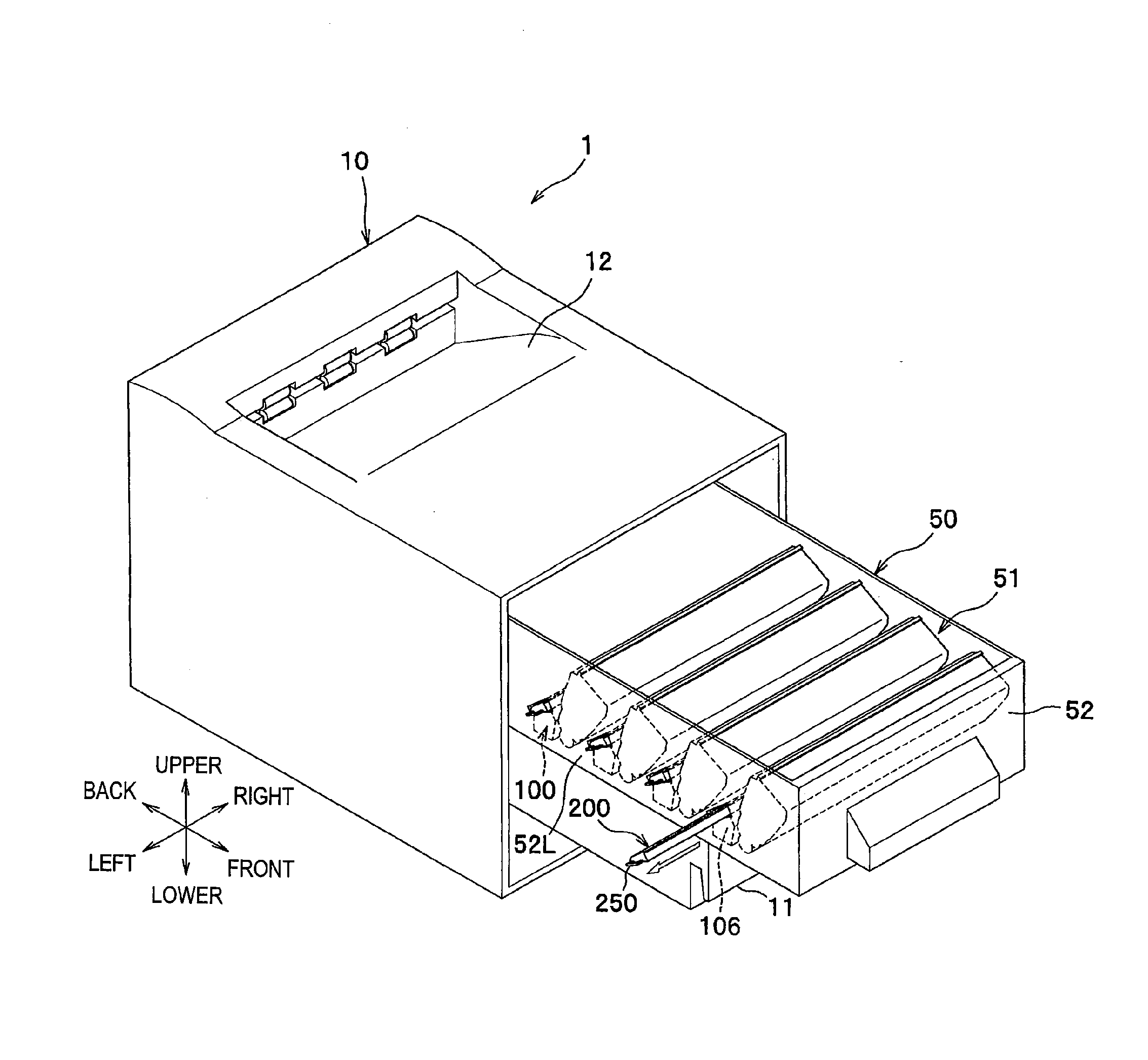
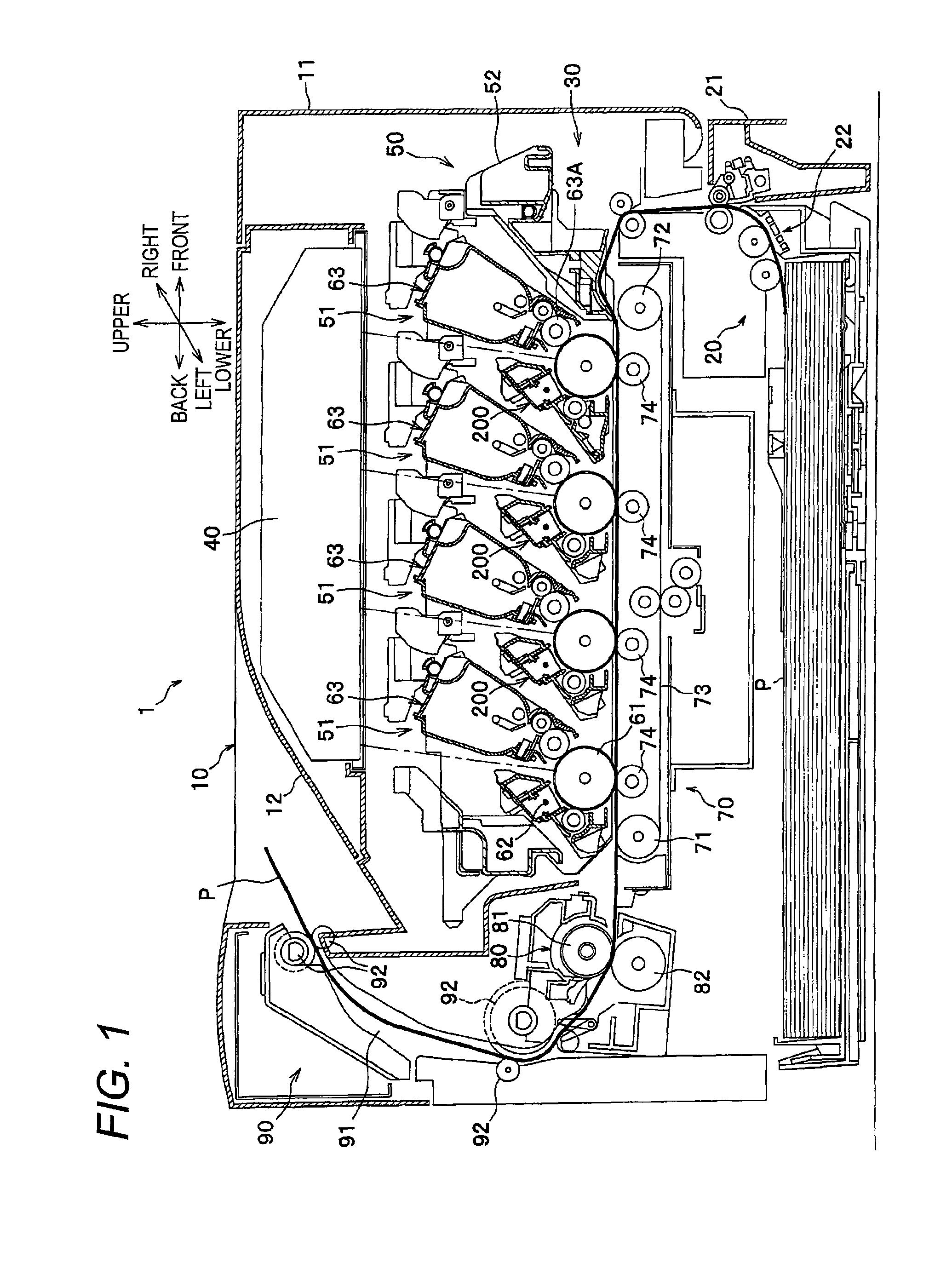
[0028]Next, an embodiment of the invention will properly be described in detail with reference to the drawings. In the reference drawings, FIG. 1 is a sectional view showing an outline configuration of a color printer as one example of an image forming apparatus. In addition, in the following description, directions are described by directions based on a user using the color printer. That is, the right side in FIG. 1 is set in the “front”, and the left side is set in the “back”, and the front side is set in the “left”, and the back side is set in the “right”. Upper and lower directions in FIG. 1 are set in the “upper and lower”.

[0029]As shown in FIG. 1, a color printer 1 comprises a sheet feeding part 20 for feeding a sheet P, an image forming part 30 for forming an image on the fed sheet P, and a sheet discharging part 90 for discharging the sheet P on which the image is formed inside a body cabinet 10 as one example of an apparatus body.

[0030]The sheet feeding part 20 is disposed ...


PUM


Abstract

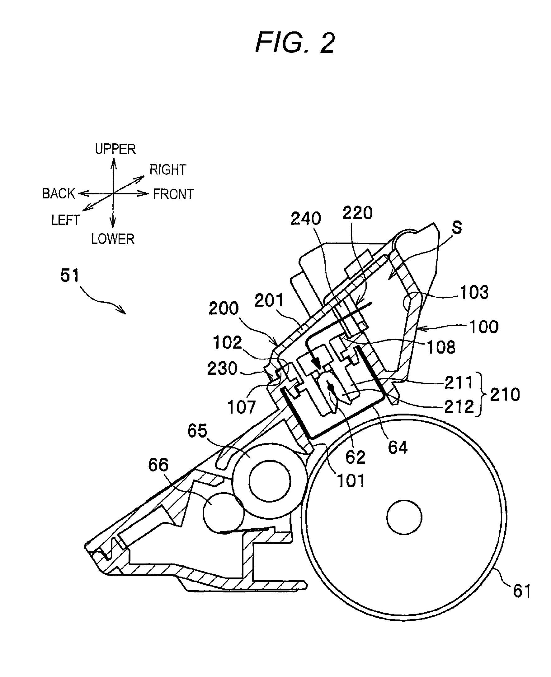
An image forming apparatus comprises a photosensitive drum, a charged wire which extends in a shaft direction of the photosensitive drum and charges the photosensitive drum by electric discharge, a frame disposed so as to surround the charged wire, the frame in which a cover side opening is formed in the side opposite to the photosensitive drum with respect to the charged wire, and a cover member disposed so as to cover the cover side opening while forming a blow path in communication with the cover side opening between the frame and the cover member. The cover member moves along the charged wire and is constructed detachably from a side surface of the frame and also a cleaning member for cleaning the charged wire is disposed.

Description

CROSS REFERENCE TO RELATED APPLICATION[0001]The present application claims priority from Japanese Patent Application No. 2008-333834 filed on Dec. 26, 2008, the disclosure of which is incorporated herein by reference in its entirety.BACKGROUND OF THE INVENTION[0002]The present invention relates to an image forming apparatus and an image forming unit.[0003]Generally, as an image forming apparatus of an electrophotography method, an apparatus in which a unit having a charged wire for charging a photosensitive body by electric discharge is detachably attached to an apparatus body is known. A configuration in which a blow hole along a charged wire is formed in a frame body surrounding the charged wire in a unit and an opening and closing lid part for covering the blow hole while forming blow space in communication with the blow hole between the frame body and the lid part is disposed is known in the related art.[0004]Also, this unit has a wire cleaner for cleaning a charged wire by maki...

Claims


Application Information

Patent Timeline
Patent Type & Authority Patents(United States)
IPC IPC(8): G03G15/02
CPCG03G15/0225G03G15/0291
Inventor SHIMIZU, TAKASHIHASHIMOTO, JUNICHI
Owner BROTHER KOGYO KK
Learn More