
Aiming post light

Inactive Publication Date: 2013-02-12
UNITED STATES OF AMERICA THE AS REPRESENTED BY THE SEC OF THE ARMY
View PDF10 Cites 0 Cited by
  • Summary
  • Abstract
  • Description
  • Claims
  • Application Information

AI Technical Summary

Benefits of technology

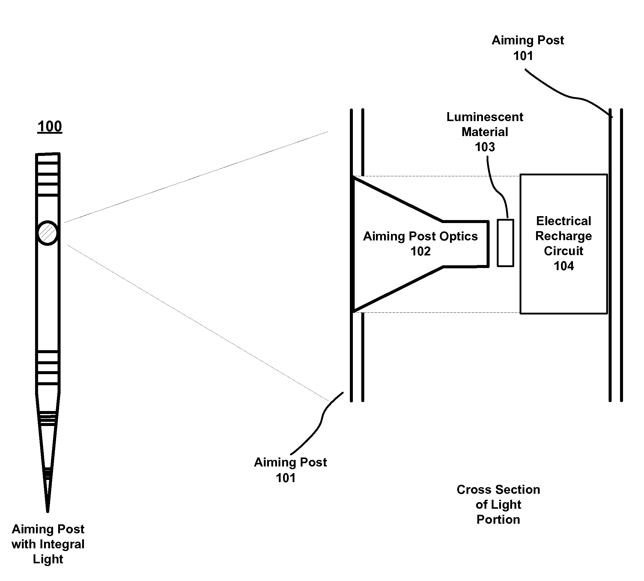
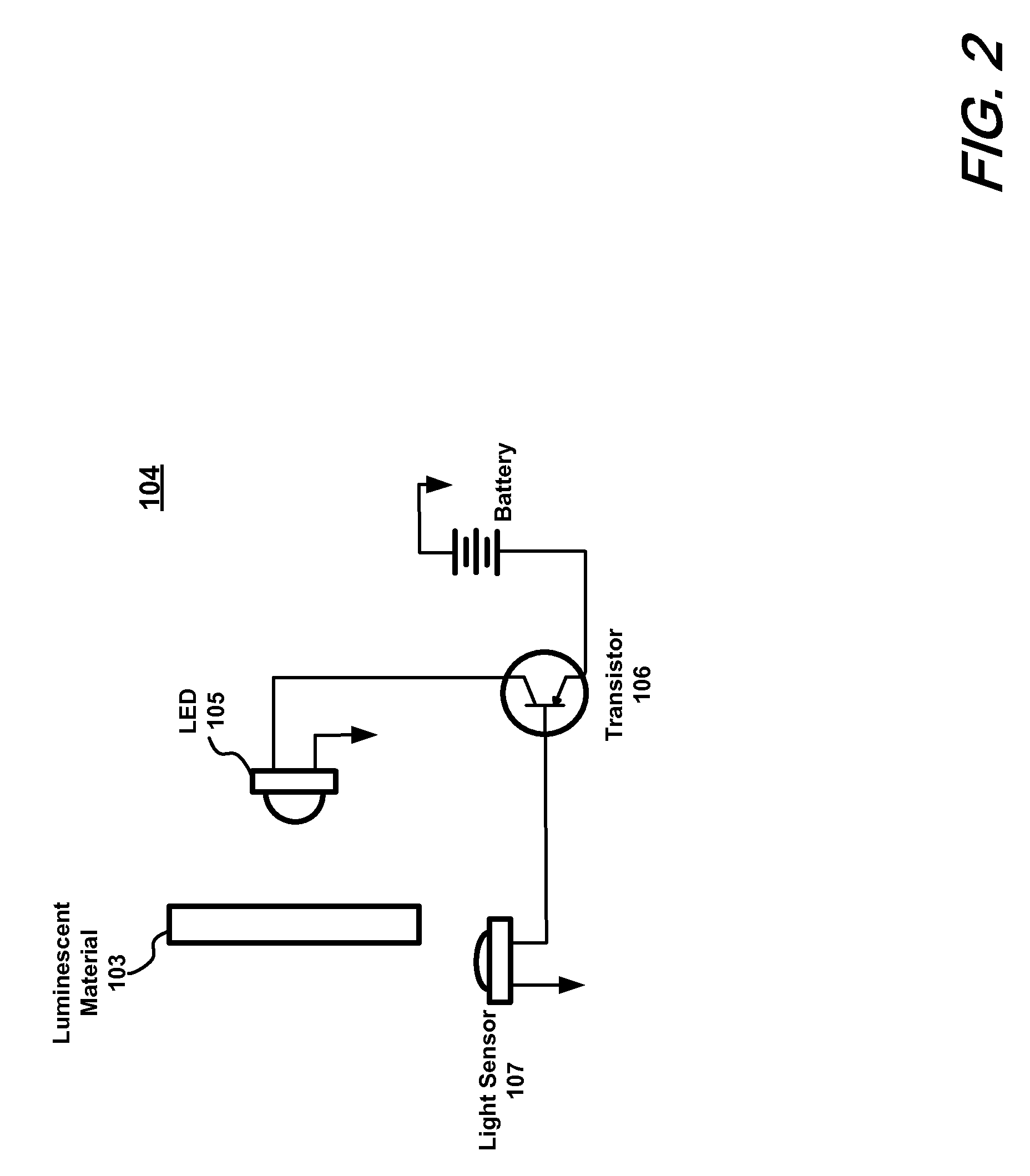
The present patent text is about an aiming post light configuration that uses a "recharge" circuit to measure the light output from the luminescent material. If the measured output is below a certain level, the circuit enables the LED or other light source to recharge the luminescent material. Once the material is recharged, the LED or other light source is turned off, and the aiming post light output is produced by the luminescent material and enhanced by the effect of the optical taper or fiber optic taper. This results in significant battery life as the LED or other powered light source is operated a minimal amount of time. Additionally, the use of the optical or fiber optic taper produces a visible light spot that is generally visible only within a direct line of sight and not peripheral, which minimizes its detection by any enemy.

Problems solved by technology

As may be appreciated, replacement of the posts, lights or batteries may be particularly hazardous when an enemy is nearby.

Method used


Image

  • Aiming post light
  • Aiming post light
  • Aiming post light

Examples


Embodiment Construction

[0009]The following merely illustrates the principles of the disclosure. It will thus be appreciated that those skilled in the art will be able to devise various arrangements which, although not explicitly described or shown herein, embody the principles of the disclosure and are included within its spirit and scope.

[0010]Furthermore, all examples and conditional language recited herein are principally intended expressly to be only for pedagogical purposes to aid the reader in understanding the principles of the disclosure and the concepts contributed by the inventor(s) to furthering the art, and are to be construed as being without limitation to such specifically recited examples and conditions.

[0011]Moreover, all statements herein reciting principles, aspects, and embodiments of the disclosure, as well as specific examples thereof, are intended to encompass both structural and functional equivalents thereof. Additionally, it is intended that such equivalents include both currently...


PUM


Abstract

An improved aiming post light configuration wherein a luminescent material in conjunction with an optical taper or other magnification structure is positioned within the body of the aiming post along with a recharge circuit which recharges the luminescent material periodically or when light output from the luminescent material falls below a predetermined threshold. Advantageously, the entire configuration may be integral to the aiming post itself.

Description

U.S. GOVERNMENT INTEREST[0001]The inventions described herein may be manufactured, used and licensed by or for the U.S. Government for U.S. Government purposes.FIELD OF THE DISCLOSURE[0002]This disclosure relates generally to the field of artillery and mortars. More particularly, it pertains to an improved aiming post light for use with—for example—field mortar systems.BACKGROUND OF THE DISCLOSURE[0003]Aiming posts are structures that are placed into the ground and used as a sighting point in aligning a weapon for indirect fire missions. Aiming posts having attached lights and are placed forward of their guns at a distance—for example—50 to 100 meters. As may be appreciated, replacement of the posts, lights or batteries may be particularly hazardous when an enemy is nearby. Accordingly, an aiming post light exhibiting a long battery life while not exposing its position to the enemy would represent a significant advance in the art.SUMMARY OF THE DISCLOSURE[0004]Such an advance in the...

Claims


Application Information

Patent Timeline
IPC IPC(8): F21V23/00
CPCF41G3/14F41G3/18
Inventor TILLINGHAST, RALPH C.
Owner UNITED STATES OF AMERICA THE AS REPRESENTED BY THE SEC OF THE ARMY
Learn More