Workpiece removing device and method

a workpiece and removing device technology, applied in the direction of programmed manipulators, instruments, programme control, etc., can solve the problems of difficult to improve the efficiency of the workpiece removal operation, the loading state of workpieces usually changes,

Active Publication Date: 2013-02-19
FANUC LTD
View PDF14 Cites 9 Cited by
  • Summary
  • Abstract
  • Description
  • Claims
  • Application Information

AI Technical Summary

Problems solved by technology

However, generally the loading state of workpieces usually changes in the next workpiece removing operation.
As a result, in the device described in JP4199264 B, there are few cases where the step of imaging with the camera is omitted, and it is difficult to improve the efficiency of the workpiece removing operation.

Method used


Image

  • Workpiece removing device and method
  • Workpiece removing device and method
  • Workpiece removing device and method

Examples


Embodiment Construction

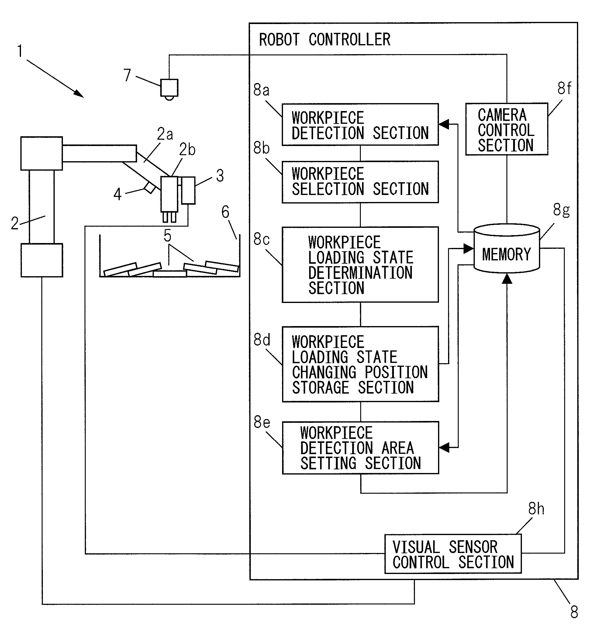
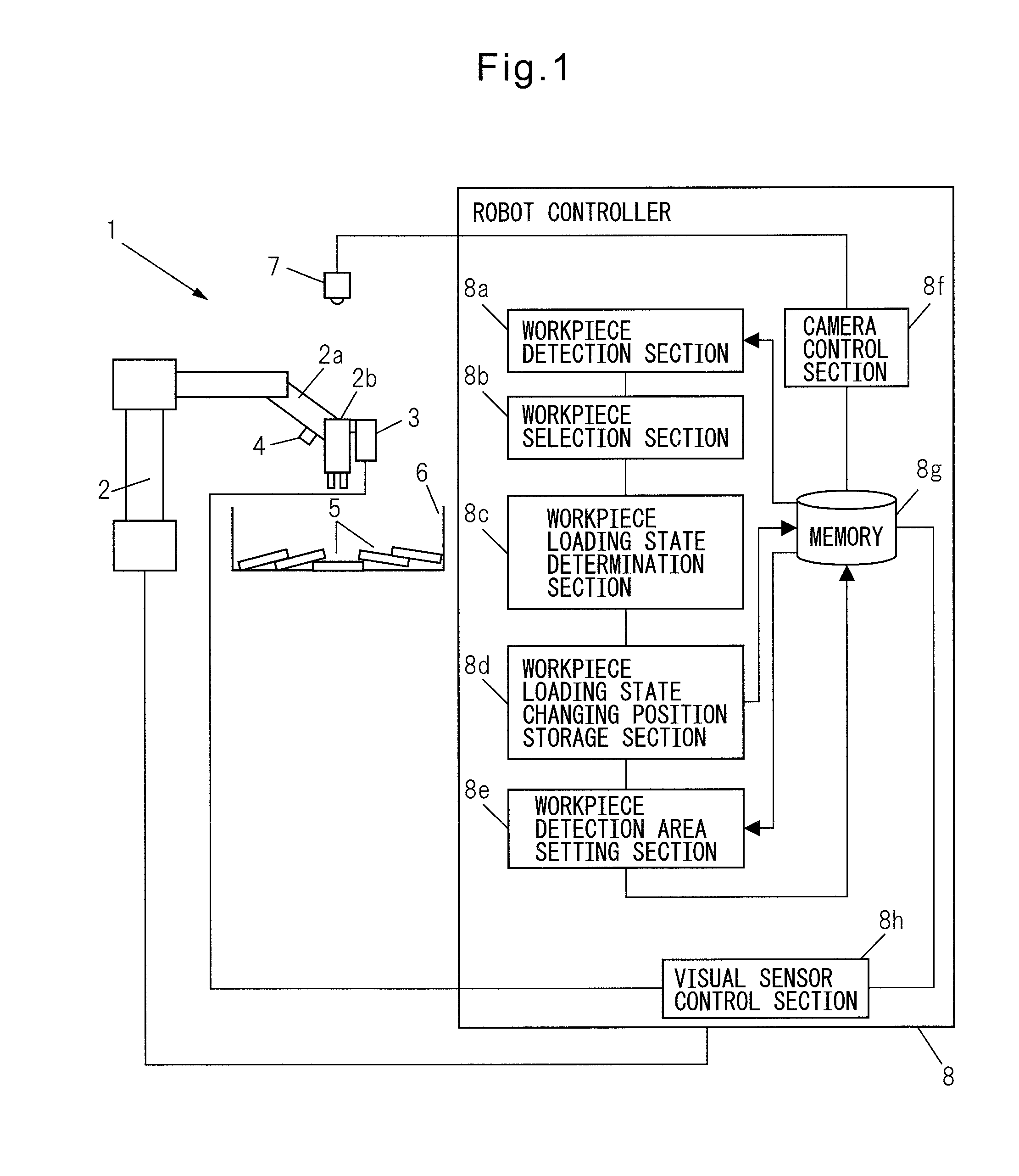
[0015]Hereinafter, an embodiment of the present invention will be described below with reference to FIGS. 1 to 5b. FIG. 1 is a view showing the general construction of a workpiece removing device 1 according to an embodiment of the present invention. A plurality of workpieces 5 which are the same kind are randomly disposed (loaded in bulk) in a container 6. The workpiece removing device 1 comprises a robot 2 for removing a selected workpiece 5 from among the plurality of workpieces 5 loaded in bulk, a camera 7 fixedly disposed above the container 6, and a robot controller 8 for controlling the robot 2 based on a camera image captured by the camera 7.

[0016]The robot 2 is a multi-joint robot having rotatable joint axes. A workpiece 5 is grasped by a robot hand 2b provided at the distal end of a robot arm 2a. A visual sensor 3 is provided on the robot hand 2b, and individual workpiece 5 is measured with the visual sensor 3. The visual sensor 3 is a 3-dimensional visual sensor of laser ...


PUM


Abstract

A workpiece removing device including a camera for imaging a workpiece loading area including a plurality of workpieces loaded in bulk; a workpiece detection section for detecting a workpiece, based on a camera image taken with the camera; a workpiece selection section for selecting a workpiece adapted to be removed, based on a detection result by the workpiece detection section; a robot for removing the workpiece selected by the workpiece selection section; a loading state determination section for determining whether a loading state of the workpieces in the workpiece loading area has changed due to a operation of the robot; and an area setting section for setting a workpiece detection area where the workpiece detection section detects a workpiece. If the loading state determination section determines that the loading state of the workpieces has changed, the area setting section sets the workpiece detection area in a peripheral area of a changing position of the loading state, i.e., in a portion of the workpiece loading area.

Description

BACKGROUND OF THE INVENTION[0001]1. Field of the Invention[0002]The present invention relates to a device and method for removing a workpiece by using a robot from among workpieces loaded in bulk in a container.[0003]2. Description of the Related Art[0004]There is a known device in which an image of an entire area of a plurality of workpieces arranged randomly (loaded in bulk) in a container is captured with a camera, and based on the captured image, workpieces are detected and removed a workpiece automatically by using a robot manipulator. In the device described in Japanese Patent Publication No. 4199264 (JP4199264B), it is determined whether or not the loading state of workpieces in a container has changed. Then, if it is determined that the loading state has not changed, without imaging the loaded workpieces in the next workpiece removing operation, a workpiece is detected based on the image captured previously. As a result, the step of imaging with the camera is omitted, and th...

Claims


Application Information

Patent Timeline
Patent Type & Authority Patents(United States)
IPC IPC(8): G06F7/00
CPCB25J9/1679B25J9/1697G05B2219/40053
Inventor BAN, KAZUNORIKUMIYA, HIDETOSHIANDO, TOSHIYUKI
Owner FANUC LTD
Why Eureka
Try Eureka