Pressure reinforced plastic container having a moveable pressure panel and related method of processing a plastic container
What is Al technical title?
Al technical title is built by PatSnap Al team. It summarizes the technical point description of the patent document.
a technology of pressure panel and plastic container, which is applied in the field of plastic containers, can solve the problems of reducing the volume of plastic containers, cluttering the sidewall of containers, and limiting the number of shapes and configurations
Inactive Publication Date: 2013-02-26
CO2 PAC
View PDF264 Cites 29 Cited by
Summary
Abstract
Description
Claims
Application Information
AI Technical Summary
This helps you quickly interpret patents by identifying the three key elements:
Problems solved by technology
Method used
Benefits of technology
[0006]In summary, the present invention is directed to a plastic container having a structure that reduces the internal volume of the container in order to create a positive pressure inside the container. The positive pressure inside the container serves to reinforce the container, thereby reducing the need for reinforcing structures such as ribs in the sidewall. This allows the plastic container to have the approximate strength characteristics of a glass container and at the same time maintain the smooth, sleek appearance of a glass container.
[0007]In one exemplary embodiment, the present invention provides a plastic container comprising an upper portion including a finish adapted to receive a closure, a lower portion including a base, a sidewall extending between the upper portion and the lower portion, wherein the upper portion, the lower portion, and the sidewall define an interior volume for storing liquid contents. A pressure panel is located on the container and is moveable between an initial position and an activated position, wherein the pressure panel is located in the initial position prior to filling the container and is moved to the activated position after filling and sealing the container. Moving the pressure panel from the initial position to the activated position reduces the internal volume of the container and creates a positive pressure inside the container. The positive pressure reinforces the sidewall.
[0008]According to another exemplary embodiment, the present invention provides a plastic container comprising an upper portion having a finish adapted to receive a closure, a lower portion including a base, and a sidewall extending between the upper portion and the lower portion, a substantial portion of the sidewall being free of structural reinforcement elements, and a pressure panel located on the container and moveable between an initial position and an activated position. After the container is filled and sealed, the sidewall is relatively flexible when the pressure panel is in the initial position, and the sidewall becomes relatively stiffer after the pressure panel is moved to the activated position.
[0009]According to yet another exemplary embodiment, the present invention provides a method of processing a container comprising providing a container comprising a sidewall and a pressure panel, the container defining an internal volume, filling the container with a liquid contents, capping the container to seal the liquid contents inside the container, and moving the pressure panel from an initial position to an activated position in which the pressure panel reduces the internal volume of the container, thereby creating a positive pressure inside the container that reinforces the sidewall.
Problems solved by technology
While known reinforcing structures usually provide the necessary strength, they tend to clutter the sidewall of the container and detract from the desired smooth, sleek appearance of a glass container.
In addition, the known reinforcing structures often limit the number of shapes and configurations that are available to bottle designers.
Method used
Image
Click on the blue label to locate the original text in one second.
Reading with bidirectional positioning of images and text.
Examples
Embodiment Construction
[0029]Embodiments of the invention are discussed in detail below. In describing embodiments, specific terminology is employed for the sake of clarity. However, the invention is not intended to be limited to the specific terminology so selected. While specific exemplary embodiments are discussed, it should be understood that this is done for illustration purposes only. A person skilled in the relevant art will recognize that other components and configurations can be used without departing from the spirit and scope of the invention. All references cited herein are incorporated by reference as if each had been individually incorporated.
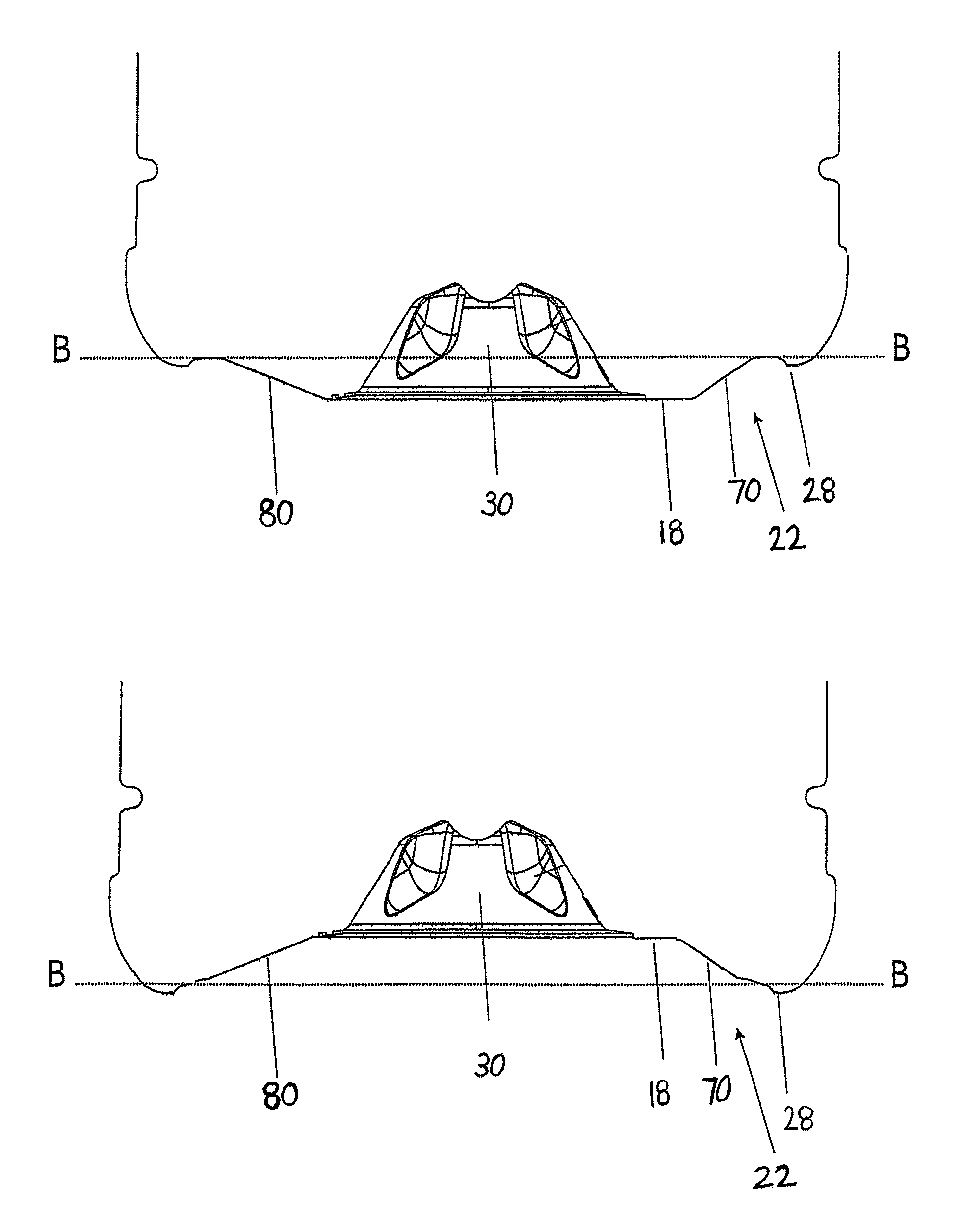
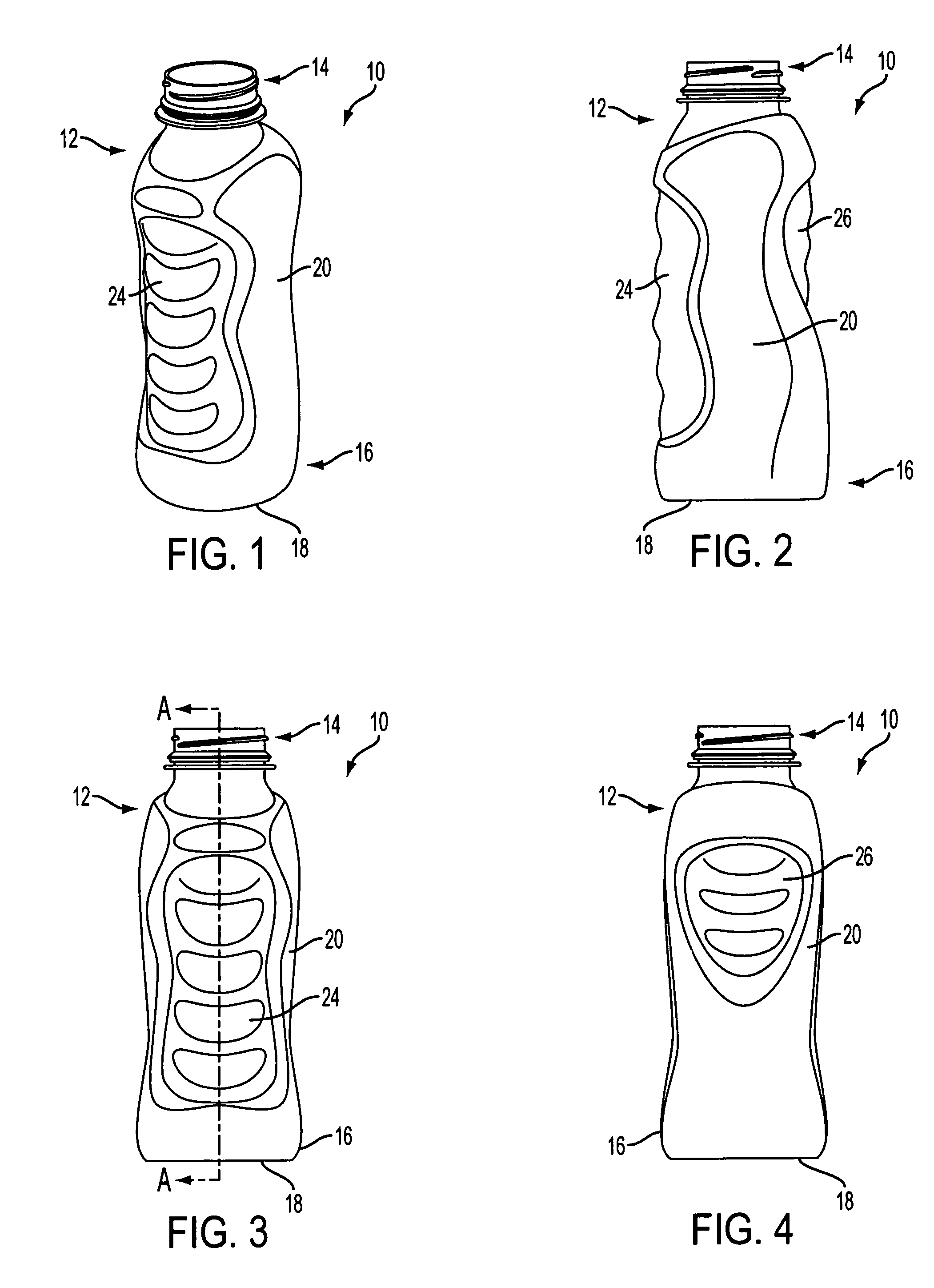
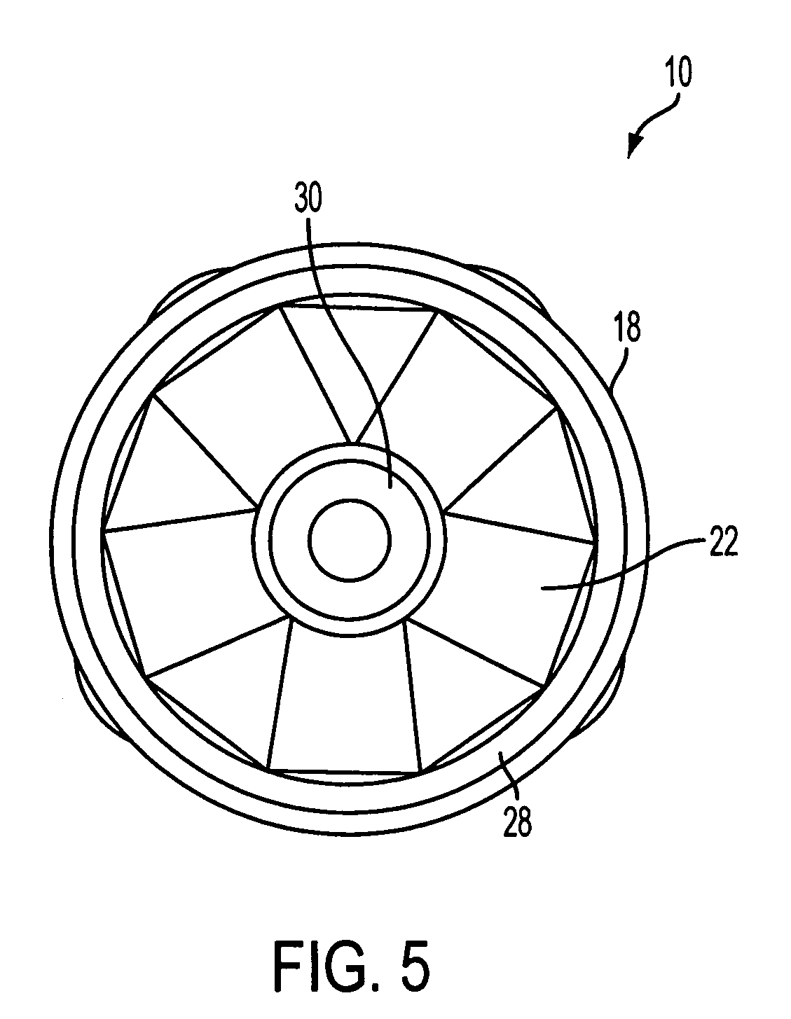
[0030]The present invention relates to a plastic container having one or more structures that allow the internal volume of the container to be reduced after the container has been filled and sealed. Reducing the internal volume of the container may result in an increase in pressure inside the container, for example, by compressing the headspace of the f...
PUM
Property
Measurement
Unit
angle
aaaaa
aaaaa
angle
aaaaa
aaaaa
angle
aaaaa
aaaaa
Abstract
A plastic container comprises an upper portion including a finish adapted to receive a closure, a lower portion including a base, and a sidewall extending between the upper portion and the lower portion. The upper portion, the lower portion, and the sidewall define an interior volume for storing liquid contents. The plastic container further comprises a pressure panel located on the container and moveable between an initial position and an activated position. The pressure panel is located in the initial position prior to filling the container, and is moved to the activated position after filling and sealing the container. Moving the pressure panel from the initial position to the activated position reduces the internal volume of the container and creates a positive pressure inside the container. The positive pressure reinforces the sidewall. A method of processing a container is also disclosed.
Description
CROSS-REFERENCE TO RELATED APPLICATIONS[0001]The present application is a continuation-in-part of U.S. patent application Ser. No. 10 / 529,198, filed on Dec. 15, 2005, which is the U.S. National Phase of International Application No. PCT / NZ2003 / 000220, filed on Sep. 30, 2003, which claims priority of New Zealand Application No. 521694, filed on Sep. 30, 2002. The present application is also a continuation-in-part of U.S. patent application Ser. No. 10 / 566,294, filed on Jan. 27, 2006, which is the U.S. National Phase of International Application No. PCT / US2004 / 024581, filed on Jul. 30, 2004, which claims priority of U.S. Provisional Patent Application No. 60 / 551,771, filed Mar. 11, 2004, and U.S. Provisional Patent Application No. 60 / 491,179, filed Jul. 30, 2003. The entire contents of the aforementioned applications are incorporated herein by reference.BACKGROUND OF THE INVENTION[0002]1. Field of the Invention[0003]The present invention relates generally to plastic containers, and mo...
Claims
Application Information
Patent Timeline
Application Date:The date an application was filed.
Publication Date:The date a patent or application was officially published.
First Publication Date:The earliest publication date of a patent with the same application number.
Issue Date:Publication date of the patent grant document.
PCT Entry Date:The Entry date of PCT National Phase.
Estimated Expiry Date:The statutory expiry date of a patent right according to the Patent Law, and it is the longest term of protection that the patent right can achieve without the termination of the patent right due to other reasons(Term extension factor has been taken into account ).
Invalid Date:Actual expiry date is based on effective date or publication date of legal transaction data of invalid patent.