Method and system for remotely automating cross-connects in telecom networks

a technology of remote automation and telecom network, applied in the field of modern telecommunication network, can solve the problems of one of the most significant costs faced by telecommunication providers today, the natural tendency of manual processes to be prone to errors, and the temporary loss of existing services

Inactive Publication Date: 2013-02-26
NORDIA INNOVATION
View PDF5 Cites 2 Cited by
  • Summary
  • Abstract
  • Description
  • Claims
  • Application Information

AI Technical Summary

Benefits of technology

[0011]It is a principal object of the present invention to overcome the disadvantages of the prior art to provide a solution that enables telecom service providers to eliminate many of the manual tasks associated with network management of their copper infrastructure.
[0012]Further to that respect, it is desirable to provide a method and system for remotely automating cross-connects in a telecommunication system to substantially reduce costs by eliminating the need for dispatching technicians onsite to manually add, remove, or modify cross-connects for subscriber communication lines.
[0013]It is another object of the present invention to eliminate the requirement for onsite visits by technicians for tasks such as service provisioning, fault detection and isolation, and circuit monitoring.

Problems solved by technology

Management of the copper infrastructure is a highly labour intensive process that results in one of the most significant costs faced by telecommunication providers today.
This manual process is naturally prone to errors since the technician can inadvertently make incorrect cross-connects that can delay activation of new services, or cause a temporary loss of existing services.
Over time as these wires can accumulate to become such a mishmash to the point where a complete rewiring is required.
This would impact current services and could result in increased customer dissatisfaction and leads to unnecessary operational expenditures in expensive labour costs.
In practice there may be several columns or stages of termination blocks on either side of the MDF whereby all line pairs may conceivably be connected with a jumper lines that bridge the line and Exchange blocks thereby leaving behind a disorganized jumble of wires that is often difficult to manage.
Another issue with the current manual intensive process is that technicians must often go to the distribution frame to manually analyse or test lines in the copper network.
In some instances, verifying and testing connections becomes significantly more difficult if over the years improper connections were made that were not correctly logged.
Troubleshooting then becomes inordinately tedious, time consuming and expensive.
In this vein there have been attempts in the past to automate MDFs using various technologies, each suffering from limitations that have rendered them uncompetitive and thus have not been deployed on a wide scale.
Although the use of electromechanical relays have been used in conventional telecommunications equipment for many years and have proven reliable for use in e.g. voice switches, the limited switching capacity of matrix boards constructed with relays has been a problem.
In practice it is difficult to construct large switches with relays because the size of the individual relays are relatively large.
This is mainly due to the relatively high voltage levels used that limit the level of miniaturization for mechanical devices.
Thus a MDF servicing a fair size CO may require millions of relays for suitable connectivity, would be expensive to maintain, and occupy far too much space to be economical.
Consequently, MDFs based on this technology never really got implemented for large-scale applications.
Although the robot mechanism can be extremely accurate to within tenths of millimetres, the mechanism head requires movement along three axes necessitating a drive motor structure that is relatively complex.
Furthermore, the mechanical components are subject to reliability and maintenance issues due to the numerous moving parts.
Service providers take these issues very seriously since costs can quickly escalate if the equipment constantly needs to be attended to.
In large size COs or those experiencing significant growth, reliability issues become even a greater concern and therefore the technology had never become viable for deployment on a large scale.
Another major disadvantage of the prior art solutions is their lack of flexibility to easily scale the size of deployment, since various telephone exchanges and central offices often vary widely in size.
The solutions of the prior art fail to provide adequate provisions for dealing with high growth since e.g. the size of the matrix board that a robot can traverse is generally fixed and is difficult to enlarge without completely replacing the equipment.
Such growth requires significant capital expenditures and substantially increases the complexity to the network infrastructure.
While automated cross-connecting technologies have existed for some time, none of the prior art solutions have been able to fulfil requirements for cost-effectiveness and scalability as required by telecom service providers.

Method used


Image

  • Method and system for remotely automating cross-connects in telecom networks
  • Method and system for remotely automating cross-connects in telecom networks
  • Method and system for remotely automating cross-connects in telecom networks

Examples


first embodiment

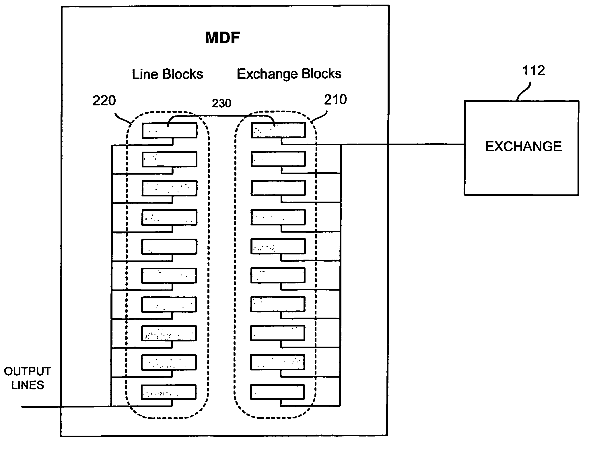
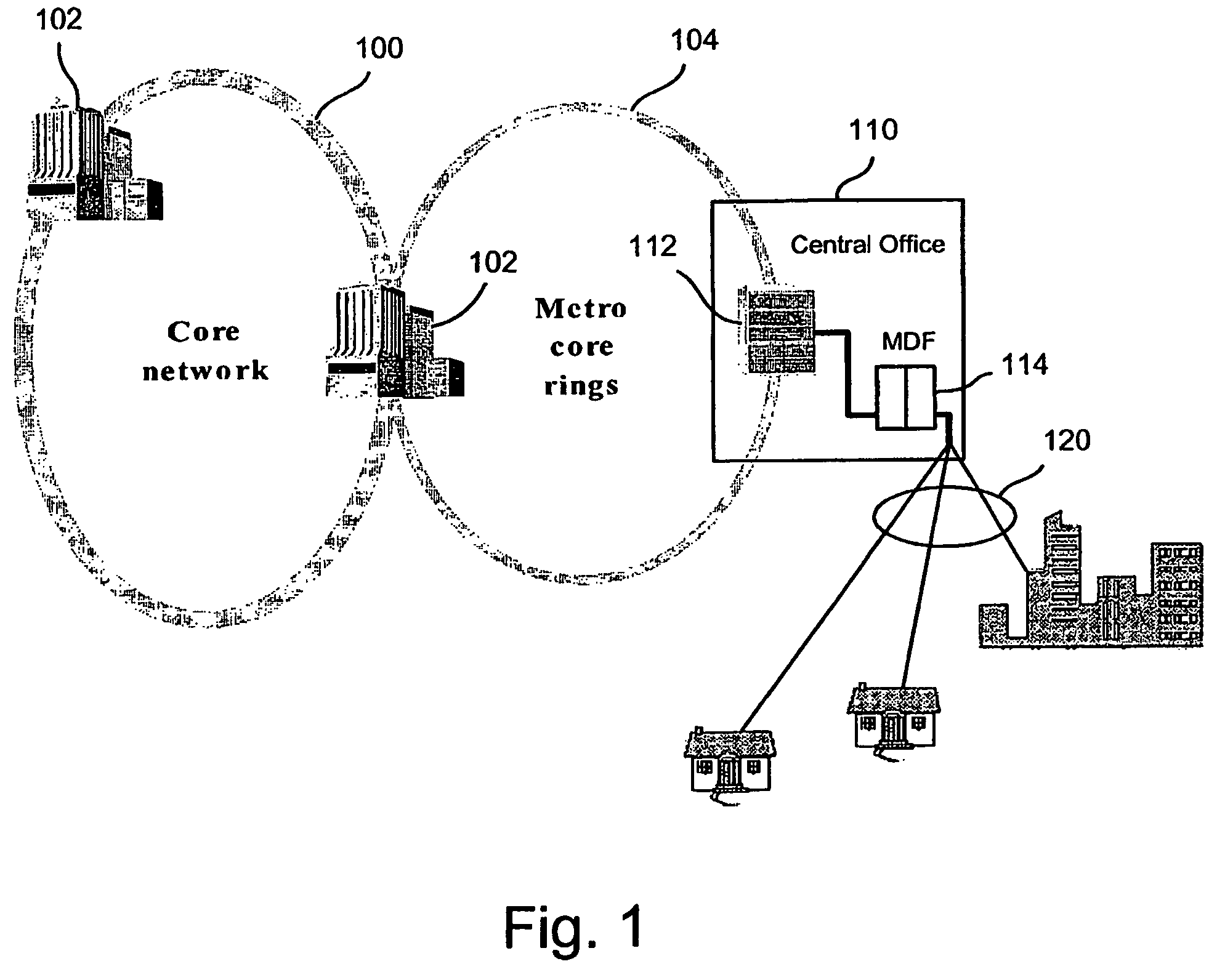
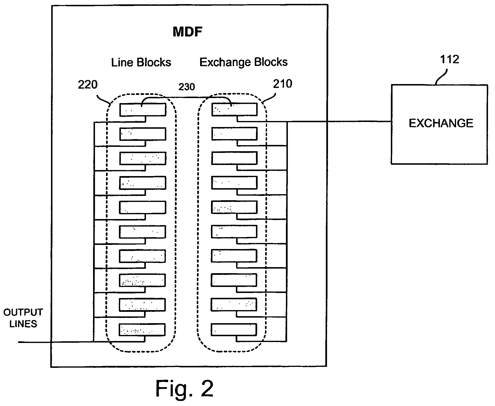
[0040]FIG. 3 illustrates an automated cross-connect system that can be controlled from a remote location 350 operating in accordance with the invention. The automated cross-connect system is a central office application that is largely concentrated with automating the cross-connections between the exchange side and the line side within the main distribution frame (MDF) 320. MDF 320 comprises a center stage 324 of cross-connect boards interconnected between the standard the exchange side MDF switch groups on the exchange side 322 and on the line side 326. The exchange side line pairs are connected to the ports at the central office switch 310, where at one end are terminated in blocks on the exchange side switch groups 322. Similarly, the output lines on the line side are terminated in blocks in the line side switch groups 326, which in the simplified layout feeds out to a street cabinet 328 typically located in the vicinity of the subscribers. In terms of capacity, these street cabi...

second embodiment

[0066]FIG. 18 shows an automated cross-connect system in accordance with the invention whereby, in addition to the MDF, non-central office cross-connect cabinets and drop point sites are also automated and controlled from a remote location. Although only one cross-connect cabinet 328 and two drop point sites 330 are shown in FIG. 18, it is to be understood that they are representative of a plurality of such cabinets 328 or drop points 330 are deployed throughout the network as remote switch groups that are capable of being supervised by a single site controller 332 within the central office. The site controller 332 includes a modem 360 communicating over a RS485 link 362, which is routed through the MDF to interconnect the site controller 332 to the automated cabinets 328 and drop point sites 330. The modem uses a point-to-point (PPP) protocol with the addition that the signal is overlaid on the voltage that is used to power the remote installation. It should be understood that the ...


PUM


Abstract

A method and system for automating cross-connects for a telecommunication system comprising a network of communication lines for connecting subscriber locations to a central office exchange 112. The communication lines extend to the subscriber locations from a main distribution frame (MDF) (320) in which a plurality of standard termination blocks are housed in the MDF for terminating the lines from to the subscriber side and lines from the exchange side, which are cross-connected in the prior art with jumper wires. In an embodiment of the invention, the cross-connects are mounted on modular cross-connect boards having mechanical switching means that are inserted into or connected to the termination blocks. Automation is achieved by selectively controlling the connection state of the cross-connects via a computer terminal (350,352) located remotely from the MDF. The system is scalable to the growth in subscriber lines within the MDF by installing additional cross-connect boards. A further embodiment includes automation of street cabinets (328) and drop point sites (330) containing cross-connect boards of the present invention.

Description

[0001]The present invention pertains generally to telecommunication networks and infrastructure, and more particularly to a method and system for remotely automating cross-connects in main distribution frames, street cabinets and drop point sites.BACKGROUND OF THE INVENTION[0002]FIG. 1 shows a typical modern telecommunication network that comprises a very high capacity back-bone optical fiber ring 100 that typically runs nearby the largest cities 102 that forms a part of the national core network. Connected to the national core network are metropolitan fiber rings 104 that surround the cities at several levels and connects to a local central office (CO) 110. The central office 110 houses switching equipment or a telephone exchange 112 and is the point to which subscriber home and business lines 120 are connected to the network on what is called a local loop. Many of these connections to residential subscribers are typically made using a pair of copper wires, also referred to as a tw...

Claims


Application Information

Patent Timeline
Patent Type & Authority Patents(United States)
IPC IPC(8): H04M3/00H04M5/00H04MH04Q1/14
CPCH04Q1/145H04Q1/136H04Q1/147
Inventor ROOS, STUREULANDER, JAN
Owner NORDIA INNOVATION
Why Eureka
Try Eureka