
Electronic device holder

a technology for electronic devices and holders, applied in the field of electronic device holders, to achieve the effect of more practical valu

Inactive Publication Date: 2013-03-05
JOW TONG TECH CO LTD
View PDF24 Cites 71 Cited by
  • Summary
  • Abstract
  • Description
  • Claims
  • Application Information

AI Technical Summary

Benefits of technology

Enables convenient and hands-free operation of electronic devices at various angles, with the ability to charge devices using an auxiliary battery when power is low, enhancing user experience and practicality.

Problems solved by technology

Once the user intends to search via the internet or read multimedia files for a long time, this cause inconvenience.

Method used


Image

  • Electronic device holder
  • Electronic device holder
  • Electronic device holder

Examples


Embodiment Construction

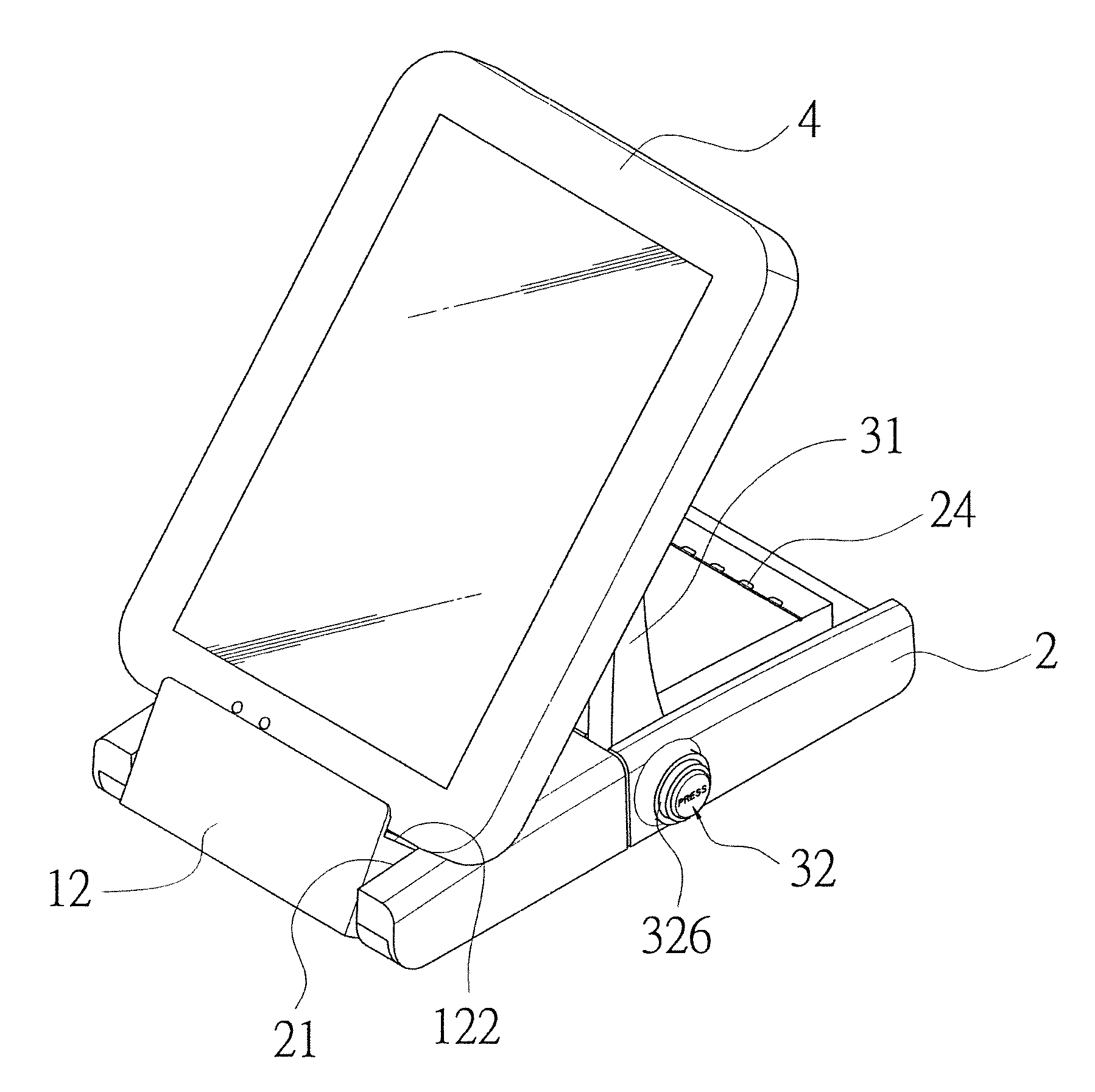
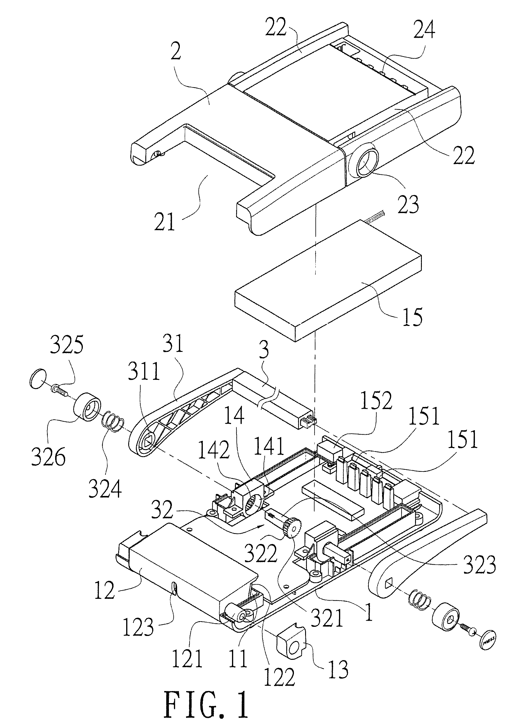
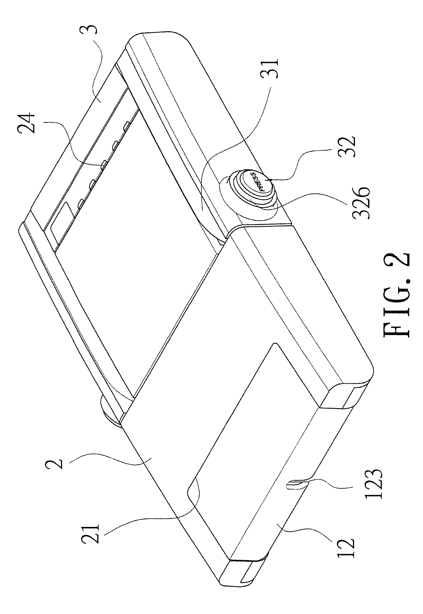
[0016]Refer to FIG. 1, an electronic device holder of the present invention includes a base 1, a top cover 2 and a support member 3.

[0017]The base 1 includes a pivot slot 11 and a support block 12 arranged movably in the pivot slot 11. Two pivot shafts 121, corresponding to each other, are respectively disposed projectingly on each of two sides of the support block 12. The pivot shaft 121 is pivotally received in a pivot block 13 on the base 1. The support block 12 includes a groove 122 disposed on a top end and a through hole 123. An assembly block 14, having a pivot hole 141 on an inner side and a locking hole 142 on an outer side, is arranged at each of two sides of the base 1. The locking hole 142 has a plurality of teeth projecting from an inner surface thereof. The pivot hole 141 and the locking hole 142 are connected to each other. Moreover, an auxiliary battery 15 is mounted in the base 1 while a power indicator 151 and a charger connector 152 corresponding to the auxiliary ...


PUM


Abstract

An electronic device holder is revealed. The electronic device holder includes a base, a top cover and a support member. In use, a control member of the support member is pressed so that a locking shaft is moved inwards to push a shaft part moving into a pivot hole of an assembly block of the base. And a teeth part around the shaft part is released from teeth of a locking hole. Thus the support member can be rotated to the required position. Without any force applied to the control member, the teeth part of the shaft part is engaged with the teeth of the locking hole again due to the elastic member. Thus the support member is locked, the support block is then rotated to the required position and an electronic device is leaning against the support member. Therefore users can use electronics conveniently, without holding them in hands.

Description

BACKGROUND OF THE INVENTION[0001]1. Field of the Invention[0002]The present invention relates to an electronic device holder, especially to an electronic device holder used to support and lock an electronic device so that users can operate electronic devices such as tablet personal computers, or smart phones conveniently without holding the electronic device in hands. The electronic device holder has more practical value.[0003]2. Description of Related Art[0004]With the rapid development of technology, various types of easy-to-use electronic devices have been provided. Among them, personal electronics such as mobiles phones and tablet personal computers have become our daily essentials, not only used to arrange schedules and process various data, but also to carry out searches via the internet. Moreover, people can also use these electronics to display multimedia information for entertainment.[0005]Although the above personal electronic devices can achieve various effects the users ...

Claims


Application Information

Patent Timeline
Patent Type & Authority Patents(United States)
IPC IPC(8): A47G1/24
CPCG06F1/1632H04M1/04G06F1/166H04M1/0214
Inventor LIN, CHUNG-HUNG
Owner JOW TONG TECH CO LTD
Learn More