Portable charging equipment

a charging equipment and portability technology, applied in the direction of current conducting connection, cell components, batteries, etc., can solve the problems of failure of battery powered electronic products to be reused, users failing to find mains electricity recharge sockets, etc., and achieve the effect of increasing practical valu

Active Publication Date: 2012-09-25
LIU YUN ZHAO
View PDF9 Cites 1 Cited by
  • Summary
  • Abstract
  • Description
  • Claims
  • Application Information

AI Technical Summary

Benefits of technology

[0007]The portable charging equipment of this invention essentially has a socket provided on side edge of a backup battery and a plug correspondingly provided on a charger device. A recessed arc portion formed on the bottom surface of the charger device is abutted on the peripheral outer edge of the backup battery. A boost unit provided in the charger device is electrically connected to the plug, and a lead wire connected to the boost unit has an output terminal provided on the other end. A tightening strap body is attached to one side of the charger device, in which a bonding end is formed on one surface at front segment of the tightening strap body and an adjustable fixing end is correspondingly formed on the other surface at rear segment of the same. The backup battery and the charger device can be inseparably affixed together by the fastening action of the tightening strap body. In this manner, the portable charging equipment can be taken along easily with users and is very handy to supply power to charge an electronic product to full power level whenever its battery power is exhausted. It can increase more practical value in the integral embodiment and usage thereof.

Problems solved by technology

The above rechargeable battery can reach anticipated effect of recharge, however it is found in practical implementation that in some cases users fail to find socket of mains electricity for recharge purpose after the power of rechargeable battery is consumed.
This may result in failure of reuse of battery powered electronic product.

Method used


Image

  • Portable charging equipment
  • Portable charging equipment
  • Portable charging equipment

Examples


Embodiment Construction

[0015]The objects, the technical contents and the expected effectiveness of the present invention will become more apparent from the detailed description of the preferred embodiment in conjunction with the accompanying drawings.

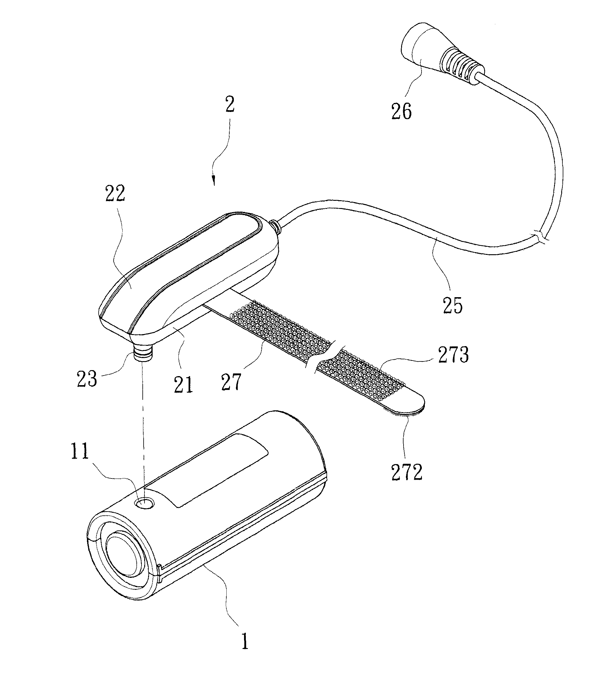
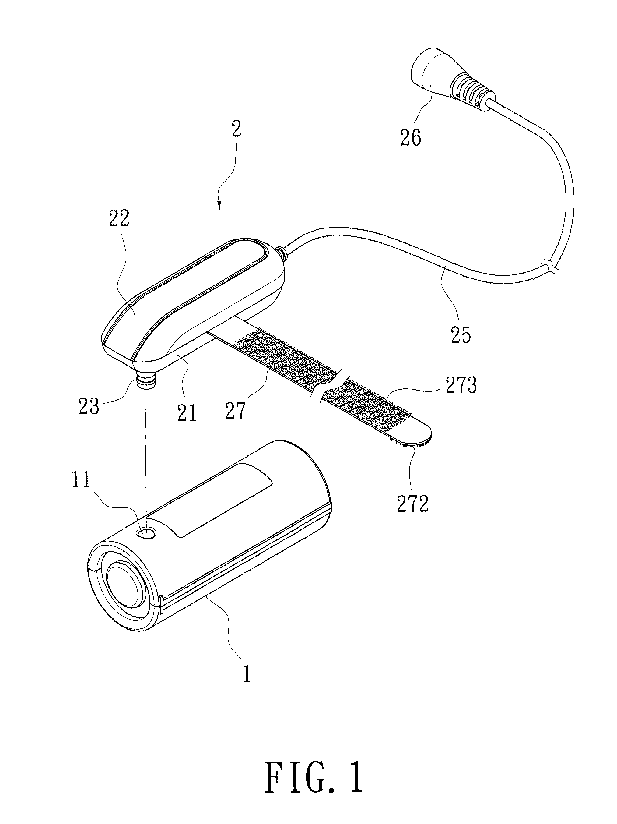
[0016]FIG. 1 is a perspective schematic view showing the portable charging equipment of the present invention. As shown in the figure, the portable charging equipment of the present invention essentially comprises a rechargeable-dischargeable backup battery (1) and a charger device (2) cooperated with each other.

[0017]The backup battery (1) can operate as ordinary battery and can be recharged by mains electricity. A socket (11) is provided on the side edge of the backup battery (1).

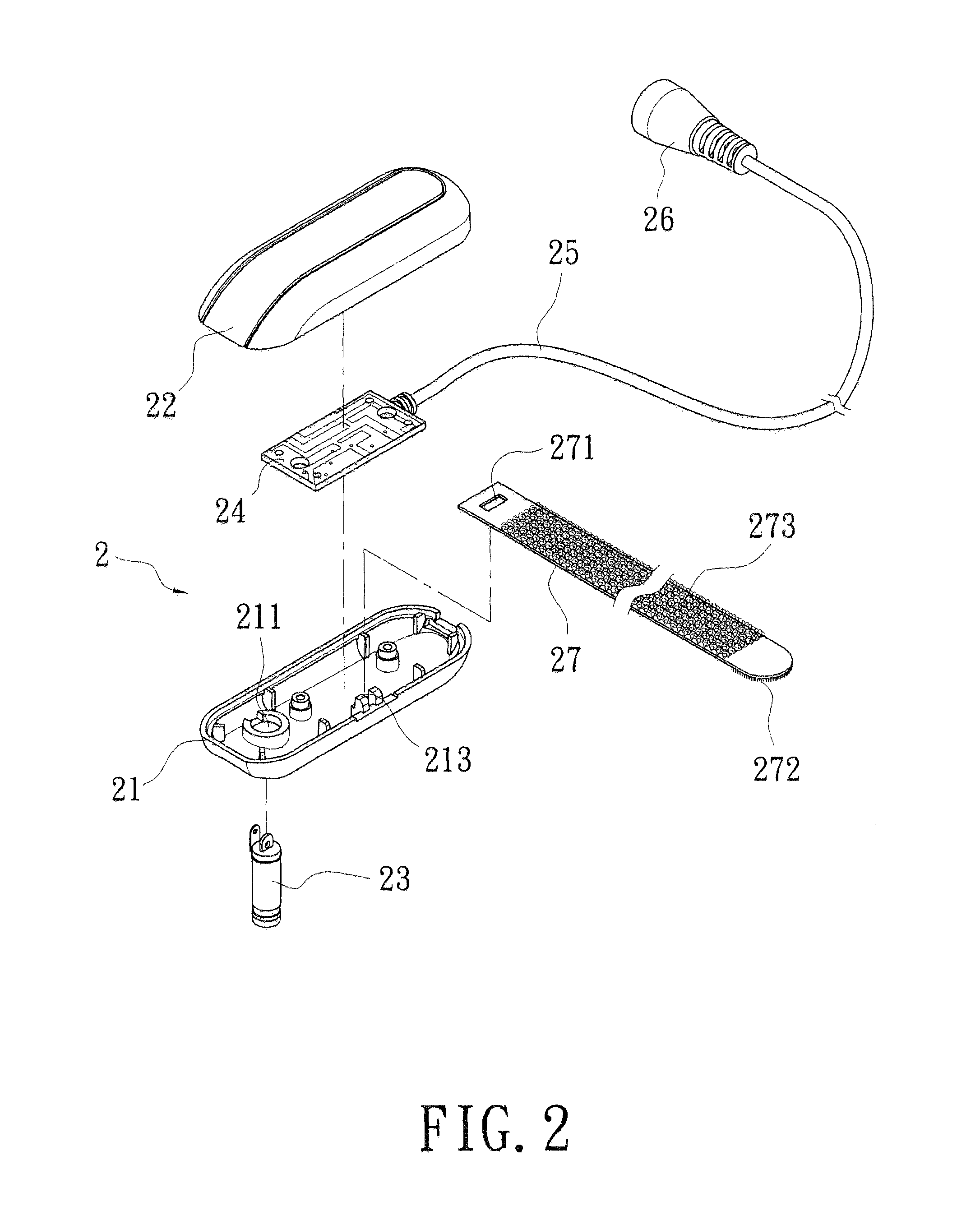
[0018]The charger device (2), as shown in FIG. 2, comprises a first housing (21) and a second housing (22) opposite to each other. The first housing (21) has a mounting aperture (211) for mounting a plug (23) therein, which is inserted into the socket (11) of the backup battery (1)...


PUM

PropertyMeasurementUnit
poweraaaaaaaaaa
structureaaaaaaaaaa

Abstract

This invention relates to a portable charging equipment in which a socket is provided on side edge of a backup battery and a plug is correspondingly provided on a charger device. A recessed arc portion formed on the bottom surface of the charger device is to abut closely against the peripheral outer edge of the backup battery. A boost unit provided in the charger device is electrically connected to the plug, and a lead wire connected to the boost unit has an output terminal provided on the other end. A tightening strap body having hook and loop structure is attached to the charger device. The backup battery and the charger device can be inseparably affixed together by the fastening action of the tightening strap body.

Description

BACKGROUND OF THE INVENTION[0001]1. Field of the Invention[0002]The present invention relates to a portable charging equipment, more particularly to a portable charging equipment which is to be carried conveniently by users, and whereby battery powered electronic product can be recharged with electricity directly to full power level in case of power emptied condition, so as to avoid inconvenience caused by unavailability of mains electricity for charging during the taking-out of the electronic product.[0003]2. Brief Description of the Prior Art[0004]Accompanying with the change of modern science and technology with each passing day, apparatuses offering greater convenience to the people have been emerging in an endless stream. Power sources available from surroundings can be utilized for driving common electronic products so as to reach anticipated effects easily. In view of the convenience contributed to human being, those electronic products have become not only popular but also a...

Claims


Application Information

Patent Timeline
Patent Type & Authority Patents(United States)
IPC IPC(8): H02J7/00H01M50/50
CPCH01M2/1055H02J7/0042H02J7/0054H01M10/46H01M2/20H02J7/0045H01M16/00H01M2220/30H02J7/342H01M50/213H01M50/50
Inventor LIU, YUN-ZHAO
Owner LIU YUN ZHAO
Why Eureka
Try Eureka